Efficient electric smelting magnesium lump waste heat recovery equipment and process

A waste heat recovery equipment and waste heat recovery technology, applied in the field of fused magnesia smelting, can solve the problems of low hot air temperature, waste of heat energy, deterioration of the surrounding environment, etc. Effect

Pending Publication Date: 2022-04-26
NORTHEASTERN UNIV +1
View PDF0 Cites 0 Cited by
  • Summary
  • Abstract
  • Description
  • Claims
  • Application Information

AI Technical Summary

Problems solved by technology

[0003] The traditional fused magnesia production process is to naturally cool the fused magnesia produced after smelting for 5 to 7 days, which not only deteriorates the surrounding environment, but also wastes a lot of heat energy. In response to the national call for energy conservation and emission reduction, To improve energy utilization, it is necessary to recover the waste heat of magnesium smelt after smelting
[0004] At present, the waste heat recovery methods for fused magnesium lumps in China can be divided into three methods: simple ventilation, water heating, and ventilation combined with water heating. Among them, the simple ventilation requires a lot of wind, which will As a result, the temperature of the hot air after heat exchange is not high, which in turn affects the effect of material preheating. If water is used to obtain heat, since the temperature of the outer surface of magnesia sand can reach 1200 ° C, if tens of degrees of hot water is used to recover the heat , does not conform to the principle of cascade energy utilization, and the recovered hot water can only be used for heating, not for preheating materials

Method used


Image

  • Efficient electric smelting magnesium lump waste heat recovery equipment and process

Examples


Embodiment Construction

[0016] The present invention will be further described below in conjunction with the accompanying drawings.

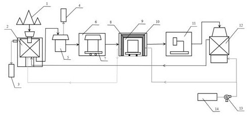
[0017] like figure 1 As shown, a high-efficiency electric fused magnesium lump waste heat recovery process and equipment, the equipment involved in the process flow includes No. 1 dust collector 3, material preheating tower 2, three-phase electric arc furnace 5, and No. 2 dust collector 4. Sealed shelling chamber 6, ferry trolley 7, waste heat recovery chamber 9, phase change heat storage material 10, phase change heat storage material shell 8, crushing device 11, high temperature heat exchange tower 12, blower 13, wherein the material is preheated The tower 2 is placed in front of the electric arc furnace 5, and the upper part of the electric arc furnace 5 is equipped with a No. 2 dust collector 4. The high-temperature flue gas generated during the smelting process is dedusted by the No. 2 dust collector 4 and used to produce dry ice. The shelling room is placed behin...


PUM


Abstract

The invention designs an efficient electric smelting magnesium lump waste heat recovery technological process and equipment. Equipment in the process comprises a dust remover, a material preheating tower, a sealed shelling chamber, a waste heat recovery chamber, a crushing device, a high-temperature heat exchange tower and an air blower. The process comprises the steps that smelted high-temperature electric smelting magnesium lumps are fed into a shelling chamber to be shelled, the shelled high-temperature magnesium lumps are fed into a waste heat recovery chamber, an Al-Si alloy phase change heat storage material is arranged in the waste heat recovery chamber, and the high-temperature magnesium lumps and the phase change material are subjected to radiation heat exchange in the waste heat recovery chamber; the high-temperature magnesium lump subjected to heat exchange is moved out of the waste heat recovery chamber and fed into a crushing device to be crushed, the crushed magnesium lump is fed into a high-temperature heat exchange tower, then air at 30 DEG C is introduced into the heat exchange tower and the waste heat recovery chamber for heat extraction, hot air at 250-860 DEG C and hot air at 380 DEG C can be obtained, the obtained hot air is used for preheating materials, the materials can be preheated to 350 DEG C, and the materials can be recycled. According to the invention, available energy for material preheating can be increased, and the material preheating temperature can be increased.

Description

technical field [0001] The invention relates to the field of electric fused magnesia smelting, in particular to a high-efficiency electric fused magnesia waste heat recovery equipment and process. Background technique [0002] Due to the continuous advancement of my country's industrialization process, the domestic energy demand is increasing day by day. In order to reduce the pressure on the supply side of the energy system, it is necessary to improve energy utilization efficiency, and reducing energy waste to improve energy efficiency is a method commonly used at present. Among them, during the magnesite smelting process, the produced magnesium fused lump contains With a large amount of sensible heat and latent heat, the temperature of the center of the smelted magnesium agglomerate is above 2800 °C, and the temperature of the outer surface of the sand is between 1000 °C and 1200 °C. [0003] The traditional fused magnesia production process is to naturally cool the fused...

Claims


Application Information

Patent Timeline
Patent Type & Authority Applications(China)
IPC IPC(8): F27D17/00C22B26/22C22B4/02
CPCF27D17/004F27D17/003F27D17/008C22B26/22C22B4/02Y02P10/20Y02P10/25
Inventor 孙添文陈韧罗志国孙野
Owner NORTHEASTERN UNIV
Why Eureka
Try Eureka