
Low-energy-consumption system and process for preparing ceramsite from solid waste

A low-energy, ceramsite technology, applied in low-energy systems and process fields, can solve problems such as insufficient heat sources, difficult to handle, and increased heat consumption, and achieve the effects of reducing system energy consumption and saving tail gas treatment costs

Pending Publication Date: 2022-04-19
TIANJIN CEMENT IND DESIGN & RES INST
View PDF6 Cites 1 Cited by
  • Summary
  • Abstract
  • Description
  • Claims
  • Application Information

AI Technical Summary

Problems solved by technology

[0007] (1) When solid waste is used as raw material to prepare ceramsite, the flue gas from the rotary kiln contains volatile organic compounds, which are difficult to deal with by conventional tail gas treatment methods
[0008] (2) When the comprehensive moisture content of the material ball is high, and the heat source provided by the original system for the flue gas from the kiln tail and the hot air from the cooler is insufficient, it is necessary to add an additional supplementary heat source to the hot blast furnace, which increases the heat consumption and complicates the system
[0009] (3) The flue gas from the dryer needs to be deodorized separately through the tail gas treatment system, the process is complicated and the cost is high

Method used


Image

  • Low-energy-consumption system and process for preparing ceramsite from solid waste
  • Low-energy-consumption system and process for preparing ceramsite from solid waste
  • Low-energy-consumption system and process for preparing ceramsite from solid waste

Examples


Embodiment 1

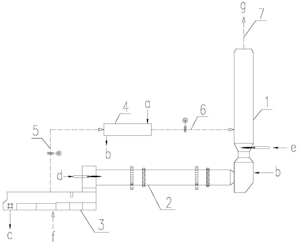
[0045] Please see attached figure 1 with attached figure 2 . The dotted line with arrows is the direction of airflow, and the solid line with arrows is the direction of material flow. The air entering the system from the burner is the primary air, the air entering the rotary kiln from the cooler is the secondary air, the air entering the pellet dryer from the cooler is the tertiary air, and the air entering the reburning furnace is also the tertiary air.

[0046] A low energy consumption system for preparing ceramsite from solid waste, the calcination system includes a reburning furnace 1, a rotary kiln 2, a cooling machine 3, and a pellet dryer 4. The cooler 3 is connected to the air inlet of the pellet dryer 4 through the front section 5 of the tertiary air duct, and the air outlet of the pellet dryer 4 is connected to the reburning furnace 1 through the rear section 6 of the tertiary air duct.

[0047] Through such a connection method, the tertiary air enters the reburn...

Embodiment 2

[0052] Using the above system, a low-energy-consumption process for preparing ceramsite from solid waste can be realized. The process is as follows:

[0053] S1: solid waste is used as the main raw material, and after the raw material is processed, wet pellet a with a moisture content of 10%-20% is obtained. The wet pellet a enters pellet dryer 4 and is dried to obtain dry pellet b;

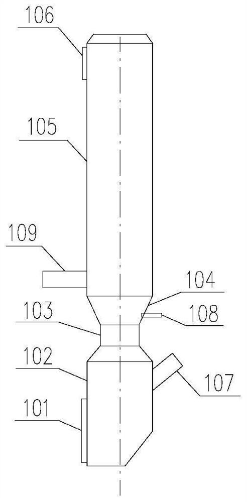
[0054] S2: The dry material ball b is fed from the material ball inlet 107 of the reburning furnace 1 and then enters the rotary kiln 2 to be calcined to obtain ceramsite. By controlling the amount of fuel d fed into the rotary kiln 2, the calcination temperature in the rotary kiln 2 is controlled to 900 -1200°C.

[0055] After the dry material ball b enters the reburning furnace 1, it exchanges heat with the flue gas from the kiln, which can achieve the purpose of preheating and is beneficial to calcination.

[0056] S3: After the ceramsite leaves the rotary kiln 2, it enters the cooling machin...

Embodiment 3

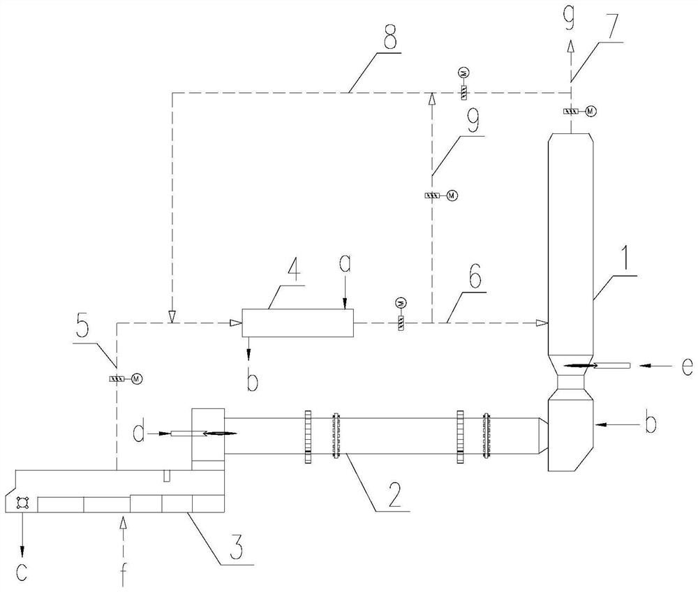
[0063] See image 3 .

[0064] Different from Embodiment 1, the high-temperature flue gas pipe 7 is also provided with a high-temperature flue gas branch pipe 8, and the high-temperature flue gas branch pipe 8 is connected to the front section 5 of the tertiary air duct. A circulating air duct 9 is also provided on the rear section 6 of the tertiary air duct, and the circulating air duct 9 is connected with the high-temperature flue gas branch pipe 8 .

[0065] The above-mentioned technical solutions in the embodiments of the present application have at least the following technical effects or advantages:

[0066] Through such a connection method, when the heat of the tertiary air of the cooler is not enough to meet the drying of the wet pellets, the flue gas from the reburning furnace can be introduced for drying. However, the temperature of this part of the flue gas is relatively high, and the temperature of the flue gas passing into the dryer should not be too high, so pa...


PUM


Abstract

The invention belongs to the technical field of environmental protection engineering, and particularly relates to a low-energy-consumption system and process for preparing ceramsite through solid waste, the low-energy-consumption system for preparing ceramsite through solid waste comprises a reburning furnace, a material ball drying machine and a cooling machine, the cooling machine is connected with an air inlet of the material ball drying machine through the front section of a tertiary air pipe, and the rear section of the tertiary air pipe is connected with a secondary air pipe; and an air outlet of the pellet dryer is connected with the reburning furnace through the rear section of the tertiary air pipe. While ceramsite is prepared, waste heat in a calcining system is fully utilized for combustion supporting, pellet drying and the like, the heat efficiency of the system is improved, and the energy consumption of the system is reduced; the problems of treatment and emission of harmful substances such as volatile organic compounds and malodorous gases generated in the flue gas when the solid wastes are digested are solved, and the low-energy-consumption system and process for preparing the ceramsite by utilizing the solid wastes are realized in low-carbon green production.

Description

technical field [0001] The invention belongs to the technical field of environmental protection engineering, and in particular relates to a low-energy-consumption system and process for preparing ceramsite from solid waste. Background technique [0002] current technology: [0003] Solid waste is an environmental pollutant that generates a large amount and is difficult to treat. Some solid waste, such as sludge, fly ash, construction spoil, and slag, are similar to clay and shale, the natural raw materials of ceramsite. After treatment, they can be For the preparation of ceramsite. [0004] When using solid waste to prepare ceramsite, solid waste such as organic pollutants, eutrophic pollutants and pathogenic microorganisms contained in sludge may produce various pollutants during the production process of ceramsite, such as smoke, sulfur dioxide, nitrogen oxides , malodorous gas, volatile organic compounds, etc. The soot, sulfur dioxide, nitrogen oxides, volatile organic...

Claims


Application Information

Patent Timeline
IPC IPC(8): F26B23/02F27D17/00F27D15/02F27B7/00F23G7/06
CPCF26B23/02F27D17/004F27D15/02F27B7/00F23G7/06Y02P40/60
Inventor 彭学平陈昌华林敏燕胡芝娟韩辉
Owner TIANJIN CEMENT IND DESIGN & RES INST
Learn More