
Flexible label laser marking machine

A laser marking machine and labeling technology, which is applied in the field of marking machines, can solve problems such as laser marking device and label misalignment, label scrapping, and increase production costs, and achieve the effect of improving accuracy and work efficiency

Pending Publication Date: 2022-04-19
湖北易同科技发展有限公司
View PDF0 Cites 0 Cited by
  • Summary
  • Abstract
  • Description
  • Claims
  • Application Information

AI Technical Summary

Problems solved by technology

[0003] The existing device transports the label to be marked to the work place through a transmission mechanism or manually, and the starting device is for label marking. When the laser marking device is affected by external vibrations when marking the label, it will cause the laser marking The device and the label are misaligned, which leads to the scrapping of the label and increases the production cost. A device that can fix the label when using the laser to mark the label is needed

Method used


Image

  • Flexible label laser marking machine
  • Flexible label laser marking machine
  • Flexible label laser marking machine

Examples


Embodiment 1

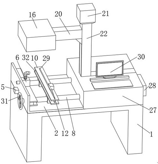
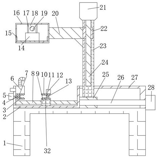
[0022] refer to figure 1 and figure 2 , a flexible label laser marking machine, including a laser device 14 and a base 1, the top of the base 1 is fixedly connected with a feeding plate 2, the top of the base 1 is provided with a clamping mechanism and a transmission mechanism, and the top of the clamping mechanism is provided with marking agency.

[0023] In the present invention, the transmission mechanism includes a screw rod 6 and a fixed column 8 that are rotatably connected to both sides of the feeding plate 2, and one end of the screw rod 6 is fixedly connected with a handle 31, and the bottom of the feeding plate 2 is slidably connected with two sliders Two 9, one slide block two 9 is threadedly connected to the side of the screw mandrel six, another slide block two 9 is slidably connected to the side of the fixed column 8, the side of the feeding plate 2 is fixedly connected with the box body 27, and the top of the box body 27 Fixedly connected with control device ...

Embodiment 2

[0029] refer to figure 1 , figure 2 and image 3 , a flexible label laser marking machine, compared with Embodiment 1, in order to make the clamping mechanism play a better clamping effect, the bottom of the upper clamping plate 10 away from the feeding plate 2 is fixedly connected with a motor two The baffle plate one 11 below 12, the top of the lower clamping plate 32 is provided with the opening one below the baffle plate one 11, the top of the lower clamping plate 32 is fixedly connected with the second baffle plate 29, and the bottom of the upper clamping plate 10 is opened There is an opening two positioned above the second baffle plate 29 .

[0030] The bottom of the upper clamping plate 10 and the top of the lower clamping plate 32 are all fixedly connected with projections 3, and the side outer wall of the feeding plate 2 away from the slider two 9 is fixedly connected with the motor one 5, and the output shaft of the motor one 5 is fixedly connected with Screw ma...


PUM


Abstract

The invention discloses a flexible label laser marking machine which comprises a laser device and a base, the top of the base is fixedly connected with a material conveying plate, the top of the base is provided with a material clamping mechanism and a transmission mechanism, a marking mechanism is arranged above the material clamping mechanism, and the transmission mechanism comprises a sixth lead screw and a fixing column which are rotationally connected to the two sides of the material conveying plate. One end of the sixth lead screw is fixedly connected with a handle, and the bottom of the conveying plate is slidably connected with two second sliding blocks. A second motor is arranged, the second motor drives a lead screw to rotate, an upper material clamping plate moves downwards, the upper material clamping plate and a lower material clamping plate clamp a label to be marked, protruding blocks on the surfaces of the upper material clamping plate and the lower material clamping plate assist devices in clamping the label, and the situation that the label moves in the marking process, and consequently the label is discarded is prevented; and by arranging the air pump, the folded air outlet pipe is bent, so that the folded air outlet pipe is aligned to a machining point.

Description

technical field [0001] The invention relates to the technical field of marking machines, in particular to a flexible label laser marking machine. Background technique [0002] Laser marking machine is to use laser beam to mark permanent marks on the surface of various materials. The effect of marking is to expose deep material through the evaporation of surface material, so as to carve exquisite patterns, trademarks and characters. Laser marking machine mainly Applied to some occasions that require finer and higher precision, such as electronic components, integrated circuits, electrical appliances, mobile communications, hardware products, tool accessories, precision instruments, glasses clocks, jewelry, auto parts, plastic buttons, building materials , PVC pipe. [0003] The existing device transports the label to be marked to the work place through a transmission mechanism or manually, and the starting device is for label marking. When the laser marking device is affecte...

Claims


Application Information

Patent Timeline
IPC IPC(8): B23K26/362B23K26/70B23K26/142B23K37/04
CPCB23K26/362B23K26/702B23K26/142B23K37/0408B23K2101/007
Inventor 文习山殷刚
Owner 湖北易同科技发展有限公司
Learn More