Steel plate auxiliary connection mold
A technology for molds and steel plates, applied in the field of auxiliary connection molds for steel plates, can solve the problems of slow construction speed and low accuracy, and achieve the effect of improving accuracy and work efficiency
- Summary
- Abstract
- Description
- Claims
- Application Information
AI Technical Summary
Problems solved by technology
Method used
Image
Examples
Embodiment 1
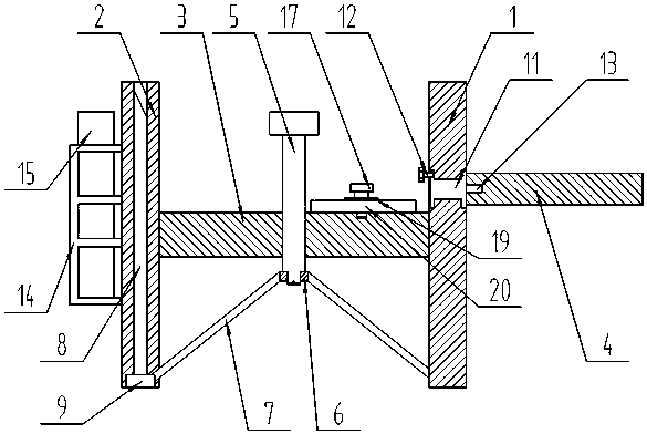
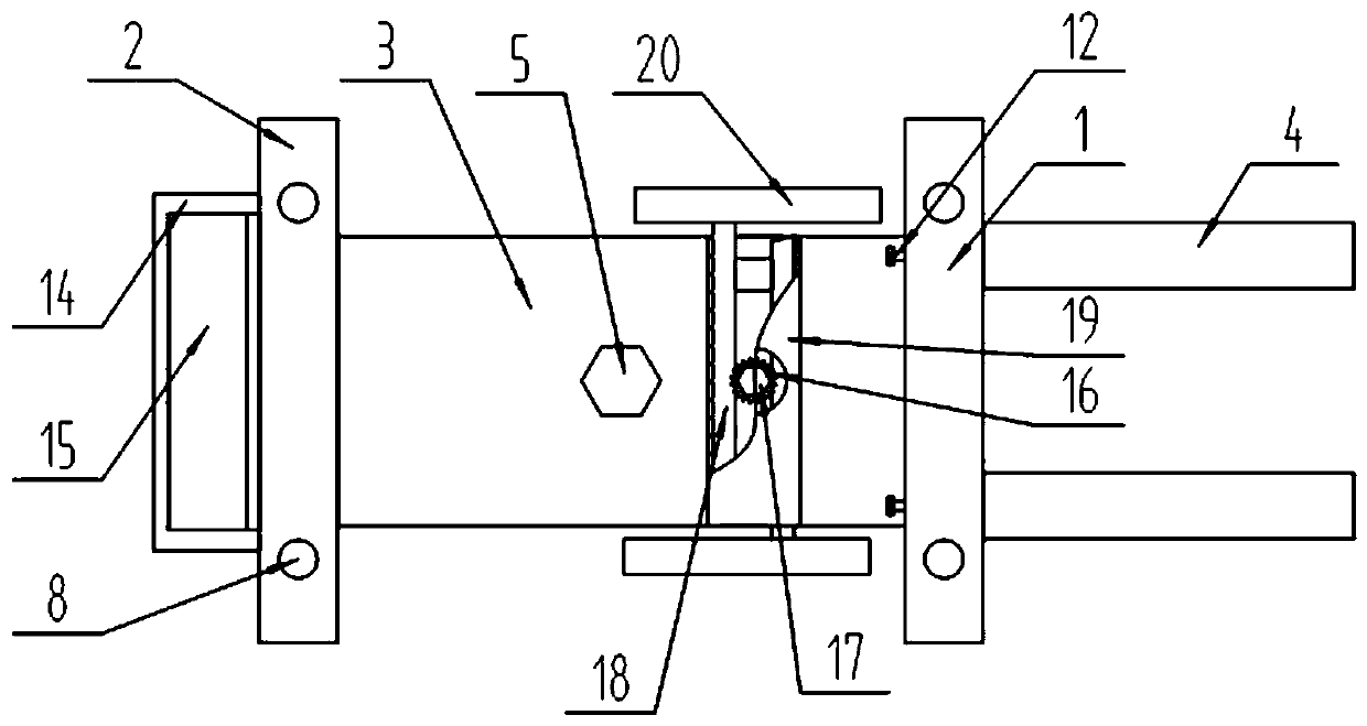
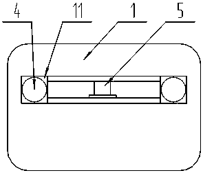
[0026] Referring to Figures 1 to 4, it is a schematic structural view of Embodiment 1 of the present invention, a steel plate auxiliary connection mold, including a first side plate 1, a second side plate 2, a horizontal plate 3, a supporting part, an adjusting part and a pair of supporting rods 4. The first side plate 1 and the second side plate 2 are respectively fixed at both ends of the horizontal plate 3, the first side plate 1 and the second side plate 2 are parallel to each other, and the support part is arranged on the first side plate 1 , Under the second side plate 2 and the horizontal plate 3, the wall surface of the first side plate 1 is slidably connected to the adjustment part, and a pair of the support rods 4 are detachably connected to the adjustment part, and the support rods 4 are located on the first side plate 1 side.
[0027] In actual use: it is supported by the first side plate 1 and the second side plate 2 to prevent it from being fixed in the groove of...
Embodiment 2
[0029] On the basis of embodiment 1, with reference to figure 1 with image 3 : the first side plate 1 and the second side plate 2 are rectangles with the same size, and the lower ends of the first side plate 1 and the second side plate 2 are located in the same plane.
[0030] In actual use: the lower ends of the first side plate 1 and the second side plate 2 are located in the same plane, which helps the support rod 4 to be parallel to the steel frame.
Embodiment 3
[0032] On the basis of embodiment 1, with reference to Figure 1~4 : the support part includes a threaded rod 5, a ring 6, a connecting frame 7, two pairs of guide columns 8 and a pair of backing plates 9, the center position of the horizontal plate 3 has a threaded hole, and the threaded rod 5 passes through the threaded hole Slide the connecting ring 6, and the threaded rod 5 is threadedly connected with the threaded hole. The connecting frame 7 is fixed under the ring 6. The lower ends of the first side plate 1 and the second side plate 2 are provided with a pair of guides perpendicular to the horizontal plate 3. Hole, guide column 8 is inserted respectively in described guide hole, each pair of said guide column 8 lower ends that are positioned at first side plate 1 and second side plate 2 respectively fix backing plate 9, described connecting frame 7 and first side The backing plate 9 under the plate 1 and the second side plate 2 is fixed.
[0033] In actual use: first t...
PUM
 Abstract
Description
Claims
Application Information
 - R&D
- Intellectual Property
- Life Sciences
- Materials
- Tech Scout
- Unparalleled Data Quality
- Higher Quality Content
- 60% Fewer Hallucinations
Browse by: Latest US Patents, China's latest patents, Technical Efficacy Thesaurus, Application Domain, Technology Topic, Popular Technical Reports.
© 2025 PatSnap. All rights reserved.Legal|Privacy policy|Modern Slavery Act Transparency Statement|Sitemap|About US| Contact US: help@patsnap.com


