
Reconfigurable low-RCS circularly polarized antenna array

A technology of circularly polarized antennas and arrays, applied in antenna arrays, antennas, resonant antennas, etc., can solve the problems of low antenna aperture efficiency, large cross-section, and high aperture, and achieve the effect of improving aperture utilization

Active Publication Date: 2022-04-15
XIDIAN UNIV
View PDF7 Cites 0 Cited by
  • Summary
  • Abstract
  • Description
  • Claims
  • Application Information

AI Technical Summary

Problems solved by technology

[0005] In order to solve the above-mentioned defects existing in the prior art, the object of the present invention is to provide a reconfigurable low RCS circularly polarized antenna array, which is used to solve the problem of low aperture efficiency and large section of the existing low RCS antenna loaded with electromagnetic metasurfaces. The problem is to achieve low profile, high aperture utilization, reconfigurable antenna, and realize the reduction of antenna RCS from the perspective of time domain stealth

Method used


Image

  • Reconfigurable low-RCS circularly polarized antenna array
  • Reconfigurable low-RCS circularly polarized antenna array
  • Reconfigurable low-RCS circularly polarized antenna array

Examples


Embodiment Construction

[0046] The present invention will be described in detail below in conjunction with the accompanying drawings and specific embodiments, where the schematic embodiments and descriptions of the present invention are used to explain the present invention, but not to limit the present invention.

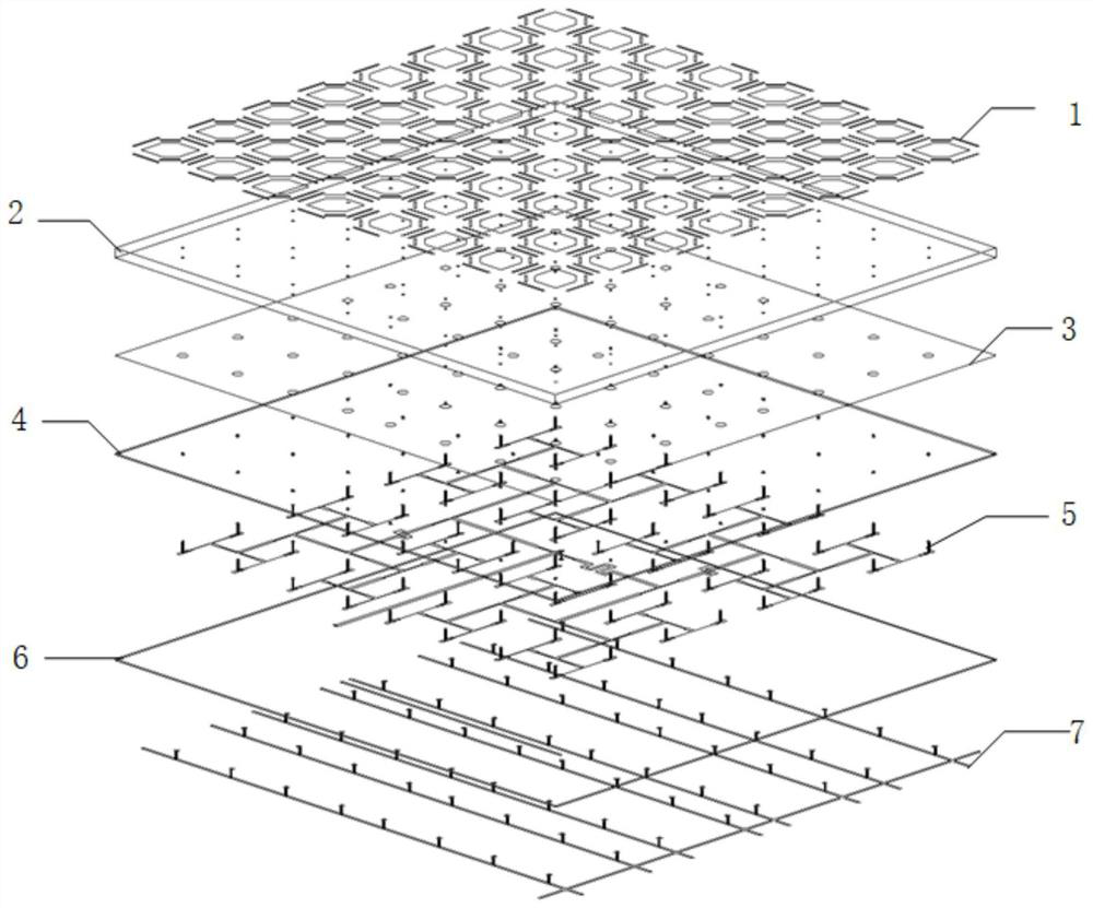
[0047] refer to figure 1 , to further describe the overall structure of a reconfigurable low RCS circularly polarized antenna array of the present invention.

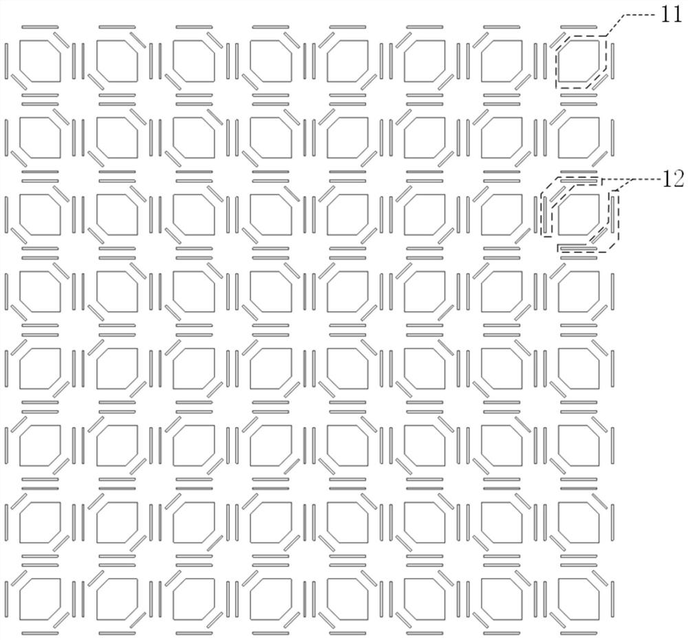
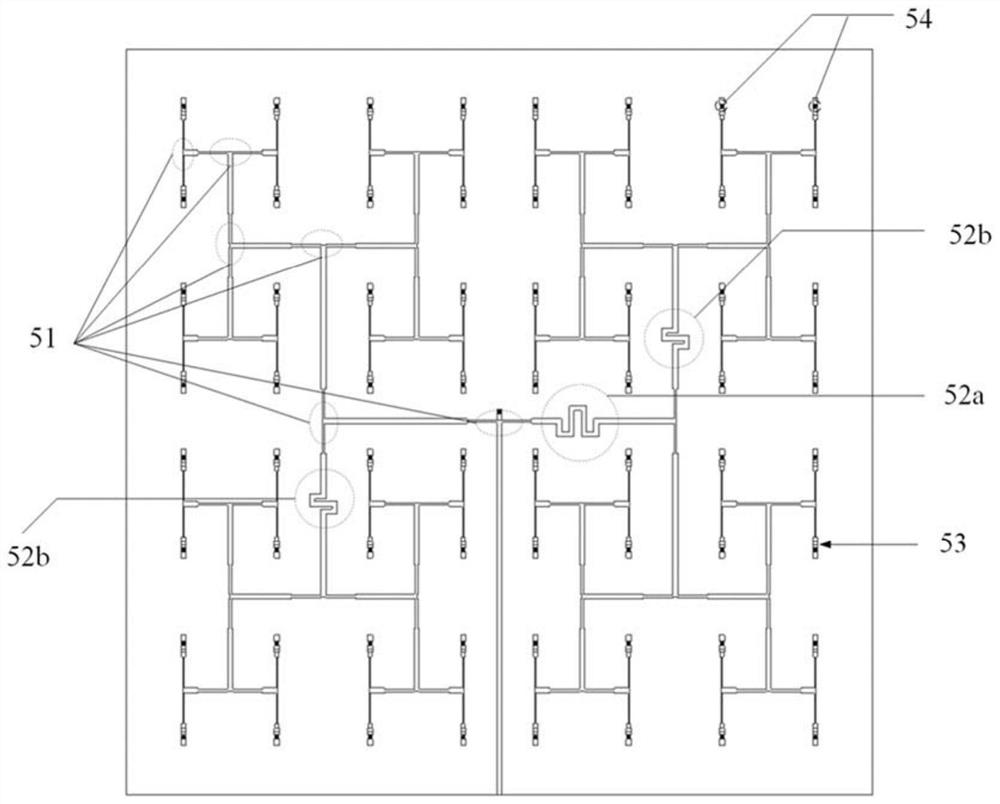
[0048] The antenna array of the present invention includes four dielectric substrates from top to bottom: a dielectric substrate 2, a metal copper-clad floor 3, a feed network dielectric substrate 4 and a diode bias network dielectric substrate 6, and a metal resonant structure 1 is attached to the dielectric substrate 2. A microstrip feed network 5 is provided between the feed network dielectric substrate 4 and the diode bias network dielectric substrate 6 , and a diode bias network 7 is provided below the diode bias network diele...


PUM

PropertyMeasurementUnit
thicknessaaaaaaaaaa
thicknessaaaaaaaaaa
thicknessaaaaaaaaaa

Abstract

The invention discloses a reconfigurable low-RCS circularly polarized antenna array, which comprises a metal resonant structure, a dielectric substrate, a metal copper-clad floor, a feed network dielectric substrate, a microstrip feed network, a diode bias network dielectric substrate and a diode bias network which are arranged in sequence, the microstrip feed network penetrates through the feed network dielectric substrate, the metal copper-clad floor and the dielectric substrate through a metal probe to be connected with the metal resonant structure, so that circular polarization radiation of the antenna array is realized; the diode bias network is connected with the microstrip feed network through a metalized through hole penetrating through the diode bias network dielectric substrate; a PIN type diode is loaded at the tail end of a microstrip feeder network to serve as an electronic switch, and when the diode is in a conducting state, an antenna array is in a radiation state; when the diode is in a cut-off state, the antenna array is in a scattering state. The antenna has the advantages of being low in profile, high in aperture utilization rate and reconfigurable, and the RCS of the antenna is reduced from the angle of time domain stealth.

Description

technical field [0001] The invention belongs to the field of communication technology, and further relates to a reconfigurable low-RCS circularly polarized antenna array in the field of antenna technology. Background technique [0002] Radar is one of the most common means of detection. During the detection process, the electromagnetic waves emitted by the radar will be reflected if they encounter obstacles. Radar detects the outside world by receiving and processing information in reflected electromagnetic waves. The Radar Cross Section (RCS) characterizes the ability of the target to generate echoes under the irradiation of electromagnetic waves emitted by the radar, and is an important indicator to measure the stealth characteristics. [0003] In the stealth design platform, taking the aircraft as an example, the air intake, cockpit and antenna are the three sources of scattering that contribute the most to the RCS of the entire system. The antenna needs to ensure its ...

Claims


Application Information

Patent Timeline
Patent Type & Authority Applications(China)
IPC IPC(8): H01Q1/38H01Q1/50H01Q23/00H01Q15/24H01Q21/00H01Q9/04
Inventor 张澎姜文赵行健雷曜宇高雨辰魏昆
Owner XIDIAN UNIV
Learn More