


Quick Research
Generate reliable direction feasibility study reports for your R&D in just a few steps.

Technical Q&A
Discover and master advanced knowledge NOW. Basics, ideas, possibilities, all at once.

Find Solutions
As an expert in R&D theories, this can generate solutions to your technical problems instantly.

Evaluate Feasibility
Analyze your overall solution with one click, know your potential R&D risks in advance.

Monitor Landscape
Get weekly tech updates, stay abreast of the latest tech innovations and key insights.
Rainwater collection and treatment system for sponge city construction
A rainwater collection and sponge city technology, applied in waterway system, sewer system, water/sewage treatment, etc., can solve the problem of underutilization of water resources, and achieve the effect of smooth drainage
- Summary
- Abstract
- Description
- Claims
- Application Information
AI Technical Summary
Problems solved by technology
Method used
Image

Examples
Embodiment 1
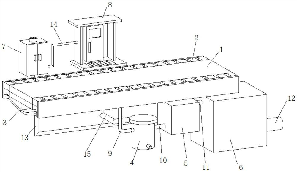
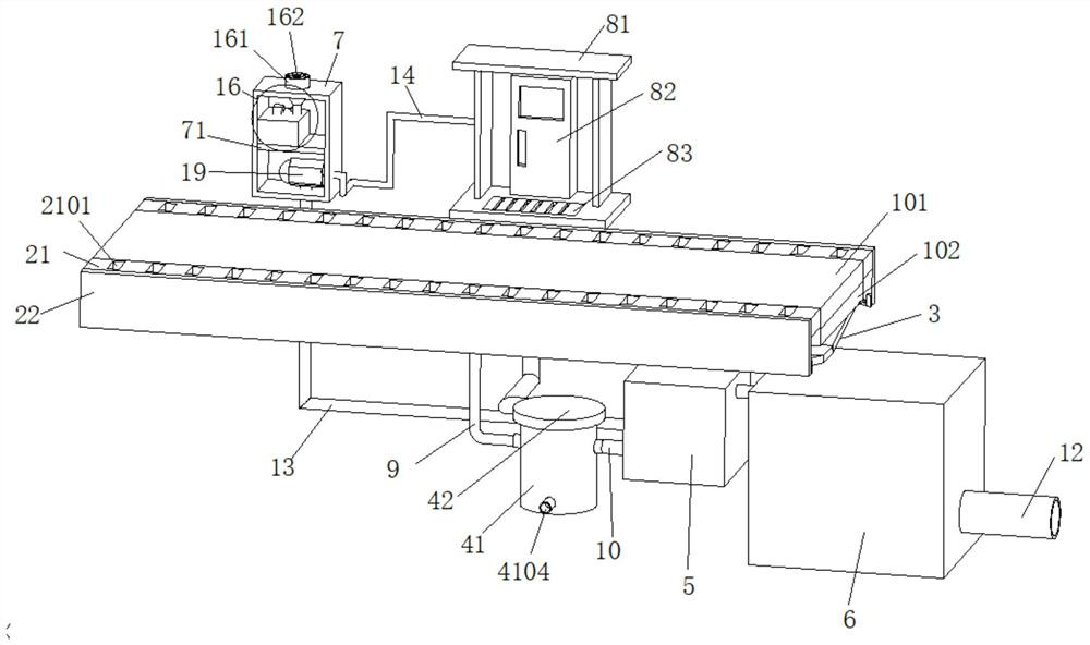
[0061] A rainwater collection and treatment system for sponge city construction, refer to the attached figure 1 , including permeable pavement 1, flow discarding device 4, percolation device 5, water storage tank 6 and master control box 7 connected in sequence through pipelines, dust isolation device 2 is arranged on both sides of permeable road surface 1, and dust isolation device 2 is installed in the general Controlled by the electric control device 16 in the control box 7, a current counter 17 is also provided on one side of the electric control device 16;
[0062] Reference attached figure 2 , the surface layer of the permeable pavement 1 is a permeable concrete surface layer 101, and the sand and gravel base layer 102 is laid under the permeable concrete surface layer 101 as a roadbed, and the rainwater on the road surface can penetrate into the permeable pavement 1 to keep the ground dry;
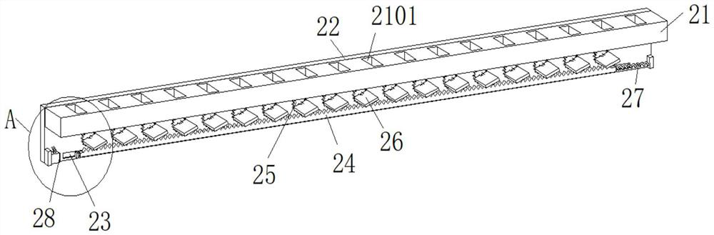
[0063] Reference attached image 3 The dust isolation device 2 includes a ba...
Embodiment 2
[0074] Embodiment 2 is slightly modified on the basis of Embodiment 1, and its similarity will not be repeated, and its main changes are:
[0075] Reference attached Figure 9 and attached Figure 10 , the water storage tank 6 is also provided with a water level display device 18 for observing the height of the water level in the tank. The water level display device 18 includes a piston cylinder 181 located at the top of the water storage tank 6, and a piston block 182 is arranged in the piston cylinder 181. In the water storage tank 6, A floating ball 3 183 is provided, and the floating ball 3 183 is connected to the piston block 182 through a connecting rod 184. An air pipe 185 is arranged on the top of the piston cylinder 181, and the other end of the air pipe 185 is connected to a U-shaped pipe 186 arranged in the master control box 7. The U-shaped tube 186 is arranged beside the water tank 163 and its inside is filled with colored liquid so as to display the liquid level...
PUM
 Abstract
Description
Claims
Application Information
 - R&D Engineer
- R&D Manager
- IP Professional
- Industry Leading Data Capabilities
- Powerful AI technology
- Patent DNA Extraction
Browse by: Latest US Patents, China's latest patents, Technical Efficacy Thesaurus, Application Domain, Technology Topic, Popular Technical Reports.
© 2024 PatSnap. All rights reserved.Legal|Privacy policy|Modern Slavery Act Transparency Statement|Sitemap|About US| Contact US: help@patsnap.com