
Airborne energy storage hydraulic system and method for bidirectional conversion of electric energy and hydraulic pressure

A hydraulic system, two-way conversion technology, applied to fluid pressure actuation system components, mechanical equipment, fluid pressure actuation devices, etc., can solve energy waste, do not have load adaptability, do not have electric energy hydraulic energy mutual conversion and emergency Energy function and other issues, to achieve good economy, reduce generator capacity demand, shorten the effect of operating time

Active Publication Date: 2022-04-12
JINCHENG NANJING ELECTROMECHANICAL HYDRAULIC PRESSURE ENG RES CENT AVIATION IND OF CHINA
View PDF10 Cites 0 Cited by
  • Summary
  • Abstract
  • Description
  • Claims
  • Application Information

AI Technical Summary

Problems solved by technology

The patent [Application No.: 201710554447.7] and the patent [Application No.: 201710554477.8] respectively propose a hydraulic and electric pressurized energy storage hatch actuation system, but they do not have the functions of mutual conversion between electric energy and hydraulic energy and emergency energy.
The patent [application number: CN202110478639.0] proposes a multi-mode hydraulic energy and electric energy bidirectional energy conversion device and method, but this method does not have load adaptability. When the main hydraulic system of the system is working, the hydraulic pump motor unit must work at Energy storage or power generation mode, will result in some degree of energy waste

Method used


Image

  • Airborne energy storage hydraulic system and method for bidirectional conversion of electric energy and hydraulic pressure

Examples


Embodiment Construction

[0031] This part is the embodiment of the present invention, which is used to explain and illustrate the technical solution of the present invention.

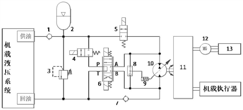
[0032] An on-board energy storage hydraulic system with two-way conversion of electric energy and hydraulic pressure, including accumulator 2, electromagnetic reversing valve 6, energy storage control valve 5, one-way variable pump-two-way motor 10, transmission device 11 and motor-generator 12 The oil supply end of the onboard hydraulic system communicates with the accumulator 2 through the oil supply check valve 1, and the accumulator 2 is connected to the one-way variable pump-two-way motor 10 through the energy storage control valve 5 as the oil outlet of the pump, and the accumulator The energy device 2 is connected to the P end of the electromagnetic reversing valve 6; the oil return end of the onboard hydraulic system is connected to the one-way variable pump-two-way motor 10 as the oil inlet port of the pump; the one-way...


PUM


Abstract

The invention belongs to the field of aircraft hydraulic systems, and discloses an airborne energy storage hydraulic system and method for electric energy hydraulic bidirectional conversion, and the system comprises an energy accumulator, an electromagnetic reversing valve, an energy storage control valve, a pump-motor, a speed change device and a motor generator; the oil supply end of the onboard hydraulic system is communicated with an energy accumulator, the energy accumulator is connected with a pump-motor through an energy storage control valve to serve as an oil outlet of the pump, and the energy accumulator is connected with the P end of an electromagnetic reversing valve; the oil return end of the onboard hydraulic system is connected with the pump-motor to serve as an oil inlet of the pump; and the pump-motor is respectively connected with the airborne actuator and the electric-generator through the speed change device. Electric pressurization energy storage is adopted on the basis of the pressure grade of the airborne hydraulic system, the energy storage efficiency is higher than that of a motor pressurization energy storage method, the instantaneous high-power airborne hydraulic user actuation time is shortened, the installed power of the aircraft hydraulic system is reduced, the system weight does not need to be increased, and the cost is reduced. And better economical efficiency is achieved, and the electric energy and hydraulic energy conversion function is achieved.

Description

technical field [0001] The application belongs to the field of aircraft hydraulic systems, and relates to a hydraulic system with energy storage function and two-way conversion of electric energy and hydraulic energy, in particular to an onboard energy storage hydraulic system and method for two-way conversion of electric energy and hydraulic energy. Background technique [0002] Multi-electricity is the development direction of modern aircraft. With the continuous development and maturity of power transmission technology, unmanned aerial vehicles have widely used EMA and other high-power electrical equipment, and large aircraft are gradually adopting power transmission systems when selecting power systems The combined action of actuators and hydraulic servo actuators improves the economy, safety, environmental protection and comfort of the aircraft. [0003] In the entire flight mission profile of the aircraft, hydraulic users such as aircraft landing gear, nose wheel steer...

Claims


Application Information

Patent Timeline
Patent Type & Authority Applications(China)
IPC IPC(8): F15B11/08F15B13/02F15B1/02F15B21/00
Inventor 聂守成杨乐王茂坤
Owner JINCHENG NANJING ELECTROMECHANICAL HYDRAULIC PRESSURE ENG RES CENT AVIATION IND OF CHINA
Learn More