Eureka AIR delivers breakthrough ideas for toughest innovation challenges, trusted by R&D personnel around the world.

Centrifugal machine for processing aluminum silicate fiber heat preservation cotton

An aluminum silicate fiber and centrifuge technology, applied in the field of centrifuges, can solve the problems of easy failure of the spinning machine, affecting the spinning effect, uneven melt, etc., so as to improve the service life, increase the output, and improve the spinning The effect of silk fiber formation

Pending Publication Date: 2022-04-08
SHENLONG CORROSION INSULATION ENG GRP CO LTD
View PDF13 Cites 0 Cited by
  • Summary
  • Abstract
  • Description
  • Claims
  • Application Information

AI Technical Summary

Problems solved by technology

However, the feeding port of the current centrifuge is fixed, and the melt flowing on the spinning roller is uneven, which affects the spinning effect, and the existing spinning machine is prone to failure and has a short life.

Method used


Image

  • Centrifugal machine for processing aluminum silicate fiber heat preservation cotton
  • Centrifugal machine for processing aluminum silicate fiber heat preservation cotton
  • Centrifugal machine for processing aluminum silicate fiber heat preservation cotton

Examples


Embodiment 1

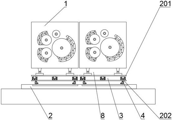
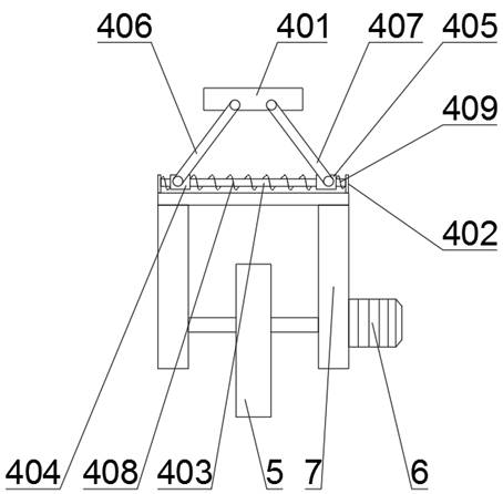
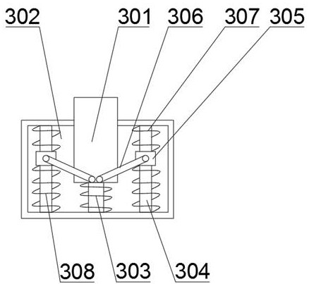
[0027] See attached Figure 1-5 As shown, it includes two centrifuges arranged side by side on the base 2. It is characterized in that the centrifuge includes a centrifuge body 1, a walking mechanism, and a first connecting plate 201 and a second connecting plate 202 that are spaced up and down and are horizontally arranged. , the second connecting plate 202 is provided with a running mechanism for driving the second connecting plate 202 to move back and forth on the track provided on the base 2, the running mechanism is connected with the second connecting plate 202 through the second shock absorbing mechanism 4, and the second connecting The plate 202 is connected to the first connecting plate 201 through the first damping mechanism 3 , and the first connecting plate 201 is connected to the centrifuge body 1 through the angle adjusting mechanism 8 .

[0028] When it is necessary to use the centrifuge body 1 to process the fiber insulation cotton, the angle adjustment mechani...

Embodiment 2

[0042] The difference between embodiment 2 and embodiment 1 is that in embodiment 2, a single or multiple resistance furnaces can be installed above the two centrifuge bodies 1, and the position and resistance of the resistance furnace can be set according to the use of the centrifuge body 1. For the flow direction of the melt in the furnace, the two centrifuge bodies 1 can be used alone, at the same time, or in combination.

[0043] When the centrifuge body 1 breaks down or needs to be overhauled, another set of centrifuge body 1 can be used to ensure that the melt in the resistance furnace is poured into the centrifuge body 1 for work, thereby improving work efficiency.

[0044] When two centrifuge bodies 1 need to be used at the same time, it is ensured that the centrifuge bodies 1 are used at the same time, which improves the work efficiency and increases the output.

[0045] When the two sets of centrifuge bodies 1 need to be used in combination, the positions of the two ...


PUM


Abstract

The invention provides a centrifugal machine for processing aluminum silicate fiber heat preservation cotton, which comprises two centrifugal machines arranged on a base in parallel front and back, and each centrifugal machine comprises a centrifugal machine body, a walking mechanism, a first connecting plate and a second connecting plate, a walking mechanism used for driving the second connecting plate to move front and back on a rail arranged on the base is arranged below the second connecting plate, the walking mechanism is connected with the second connecting plate through a second damping mechanism, and the second connecting plate is connected with the first connecting plate through a first damping mechanism. The first connecting plate is connected with the centrifugal machine body through an angle adjusting mechanism. The centrifugal thread throwing uniformity of the centrifugal machine body is guaranteed, the thread throwing quality is guaranteed, the working efficiency of the centrifugal machine body is improved, and the working yield of the centrifugal machine body is increased.

Description

technical field [0001] The invention belongs to the technical field of centrifuges, and in particular relates to a centrifuge for processing aluminum silicate fiber thermal insulation cotton. Background technique [0002] The fiber-forming process of aluminum silicate fiber insulation cotton mainly adopts the method of melting and spinning. Under the action, the stream is broken up, gradually stretched and deformed, and spun into filamentous fibers. Finally, the fibers become thinner and longer under the action of compressed air injection. At the same time, they are cooled and solidified to form fibers and turn to the next process. [0003] The centrifuge is the core equipment of the refractory fiber production line. It flows the mineral melt melted by the resistance furnace through the orifice to the spinning roller of the centrifuge, and forms the refractory fiber cotton under the action of the centrifugal force of the spinning roller. However, the feed inlet of the curre...

Claims


Application Information

Patent Timeline
Patent Type & Authority Applications(China)
IPC IPC(8): D01D5/18D01D5/08
Inventor 周立华
Owner SHENLONG CORROSION INSULATION ENG GRP CO LTD
Why Eureka
Eureka Blog
Learn More