


Quick Research
Generate reliable direction feasibility study reports for your R&D in just a few steps.

Technical Q&A
Discover and master advanced knowledge NOW. Basics, ideas, possibilities, all at once.

Find Solutions
As an expert in R&D theories, this can generate solutions to your technical problems instantly.

Evaluate Feasibility
Analyze your overall solution with one click, know your potential R&D risks in advance.

Monitor Landscape
Get weekly tech updates, stay abreast of the latest tech innovations and key insights.
Pepper oil-water separator
A technology of oil-water separation and Chinese prickly ash, applied in the direction of oil/fat refining, fat production, etc., can solve the problems of difficult to intuitively determine the timing of oil discharge, low production efficiency of oil-water separator, affecting the extraction process of Chinese prickly ash oil, etc. Frictional resistance, the effect of improving efficiency
- Summary
- Abstract
- Description
- Claims
- Application Information
AI Technical Summary
Problems solved by technology
Method used
Image

Examples
Embodiment 1
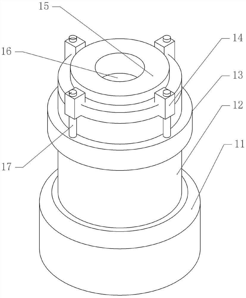
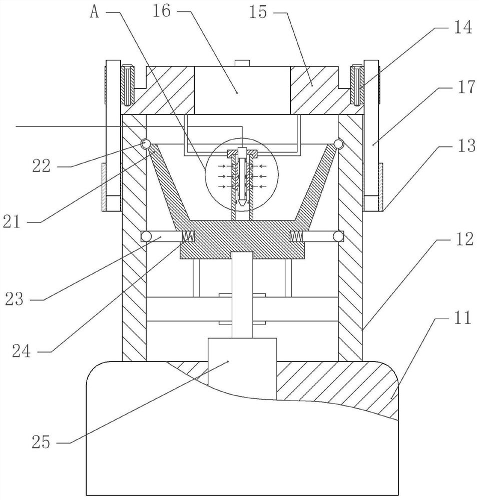
[0038] A pepper oil-water separator, as attached figure 1 , attached figure 2 And attached image 3 As shown, it includes a support seat 11 and a barrel body 12 fixed on the support seat 11. The upper opening of the barrel body 12 is provided with a cover 15 for closing the opening of the barrel body 12. Feeding port 16, cover body 15 is fixed with some stoppers 14 along its circumference, and limiter shaft 17 is all fixed on stopper block 14, and staving ring 13 that is positioned at cover body 15 belows is fixed on staving 12, and limit There are some limit holes on the position ring 13, and the limit holes are vertically slidably matched with the position limit shaft 17. In this embodiment, when the cover body 15 is installed, the limit shaft 17 is inserted into the limit hole, so that the cover plate closes the opening and the limit shaft 17 and the limit hole limit the cover plate.
[0039] In this embodiment, the barrel body 12 is provided with a separation barrel 21...
Embodiment 2
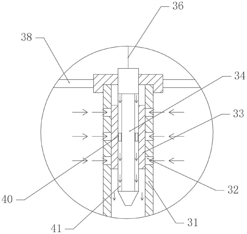
[0050] The difference between embodiment two and embodiment one is that, as attached Figure 4 And attached Figure 5 As shown, the electromagnetic reversing valve 35 is fixed on the fixed block, the inlet of the electromagnetic reversing valve 35 is connected with the nozzle 34, and an outlet of the electromagnetic reversing valve 35 is connected with the recovery pipe 36, and the recovery pipe 36 is connected with the buffer barrel 42, and the buffer Bucket 42 is communicated with negative pressure pump 43, and another outlet of electromagnetic reversing valve 35 is communicated with water pipe 37, and water pipe 37 is communicated with water bucket 44, and water bucket 44 is communicated with water pump 45.
[0051] The specific implementation process is as follows:
[0052] When the pepper oil is separated from the water, the negative pressure pump 43 communicates with the electromagnetic reversing valve 35 through the recovery pipe 36 and communicates with the nozzle 34,...
PUM
 Abstract
Description
Claims
Application Information
 - R&D Engineer
- R&D Manager
- IP Professional
- Industry Leading Data Capabilities
- Powerful AI technology
- Patent DNA Extraction
Browse by: Latest US Patents, China's latest patents, Technical Efficacy Thesaurus, Application Domain, Technology Topic, Popular Technical Reports.
© 2024 PatSnap. All rights reserved.Legal|Privacy policy|Modern Slavery Act Transparency Statement|Sitemap|About US| Contact US: help@patsnap.com