


Quick Research
Generate reliable direction feasibility study reports for your R&D in just a few steps.

Technical Q&A
Discover and master advanced knowledge NOW. Basics, ideas, possibilities, all at once.

Find Solutions
As an expert in R&D theories, this can generate solutions to your technical problems instantly.

Evaluate Feasibility
Analyze your overall solution with one click, know your potential R&D risks in advance.

Monitor Landscape
Get weekly tech updates, stay abreast of the latest tech innovations and key insights.
Gas separation membrane as well as preparation method and application thereof
A gas separation membrane and thin film technology, which is applied in separation methods, semipermeable membrane separation, and dispersed particle separation, can solve the problems of rough surface of MOFs/polymer membrane, low gas separation performance and low gas selectivity, and achieve smooth surface And the effect of no defect, good flexibility and simple preparation process
- Summary
- Abstract
- Description
- Claims
- Application Information
AI Technical Summary
Problems solved by technology
Method used
Image

Examples
specific Embodiment approach 1
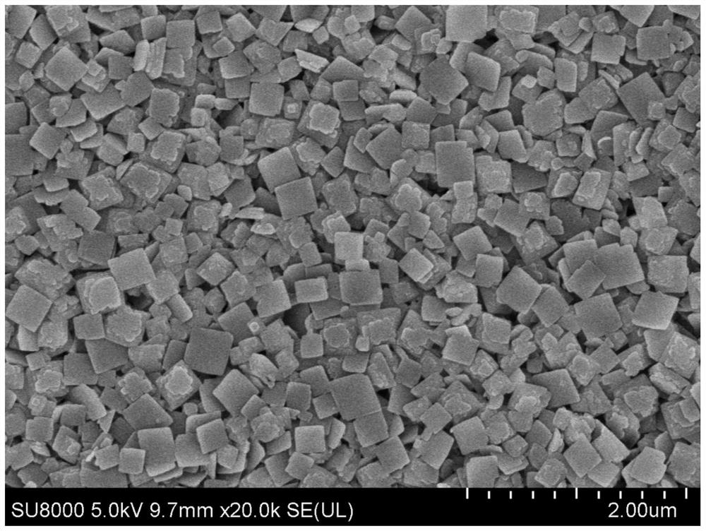
[0033] Specific embodiment one: a kind of gas separation membrane described in this embodiment, the gas separation membrane is made of two-dimensional CuBDC-NH 2Sheet-like stacked thin films prepared with polyurethane oligomers; the two-dimensional CuBDC-NH 2 It accounts for 20% to 60% of the total mass of the gas separation membrane.
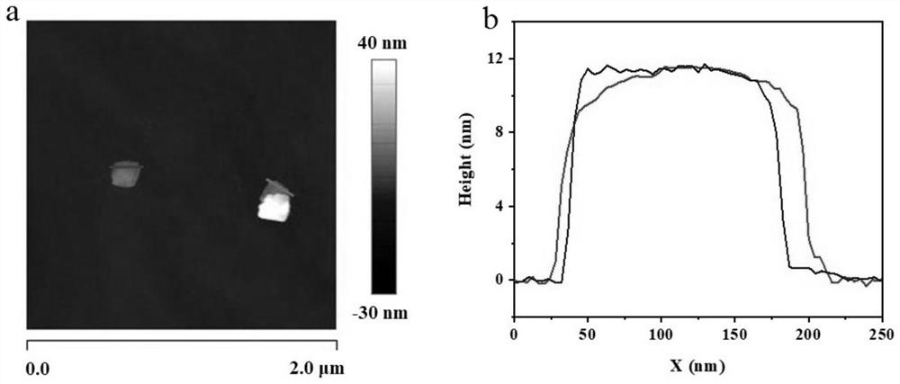
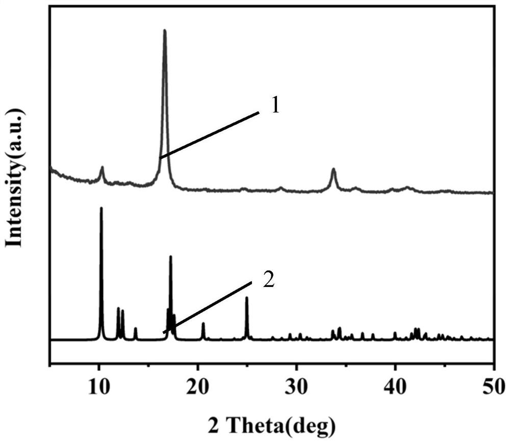
[0034] This embodiment uses two-dimensional MOFs (two-dimensional CuBDC-NH 2 ) to replace the three-dimensional MOFs. Due to the ultrathin thickness and more accessible pore channels, 2D MOFs not only have more adsorption sites, but also are easier to form thin films with fewer defects. And the selected two-dimensional CuBDC-NH 2 Compared with ordinary two-dimensional MOFs, it has a modifiable -NH 2 Functional groups, therefore, functional group modification technology can be combined with polymers (polyurethane oligomers) for polymerization reactions to further improve the performance of the resulting film.
[0035] The beneficial effect ...
specific Embodiment approach 2
[0037] Specific embodiment two: the present embodiment is a kind of preparation method of gas separation membrane, and it is carried out according to the following steps:
[0038] 1. Two-dimensional CuBDC-NH 2 Preparation of:
[0039] 1. Add anhydrous copper acetate to the mixed solution A for dissolution to obtain anhydrous copper acetate solution;
[0040] ②. Add 2-aminoterephthalic acid to the mixed solution B to dissolve to obtain a 2-aminoterephthalic acid solution;
[0041] ③. Spray the anhydrous copper acetate solution into the 2-aminoterephthalic acid solution through an ultrasonic spray device, and let it stand to obtain a solid substance, which is washed and filtered to obtain a two-dimensional CuBDC-NH 2 solid;
[0042] The amount of substance ratio of the anhydrous copper acetate in the described anhydrous copper acetate solution and the 2-aminoterephthalic acid in the 2-aminoterephthalic acid solution is 1: (1~40);
[0043] Two, the preparation of polyurethane...
specific Embodiment approach 3
[0054] Specific embodiment 3: The difference between this embodiment and specific embodiment 2 is that the mixed solution A described in step ① is formed by ultrasonic dispersion of N, N-dimethylformamide and acetonitrile, and the N, N, The volume ratio of N-dimethylformamide to acetonitrile is 1:(0.1~10). Others are the same as in the second embodiment.
PUM
| Property | Measurement | Unit |
|---|---|---|
| diffusion coefficient | aaaaa | aaaaa |
| pore size | aaaaa | aaaaa |
Abstract
Description
Claims
Application Information
 - R&D Engineer
- R&D Manager
- IP Professional
- Industry Leading Data Capabilities
- Powerful AI technology
- Patent DNA Extraction
Browse by: Latest US Patents, China's latest patents, Technical Efficacy Thesaurus, Application Domain, Technology Topic, Popular Technical Reports.
© 2024 PatSnap. All rights reserved.Legal|Privacy policy|Modern Slavery Act Transparency Statement|Sitemap|About US| Contact US: help@patsnap.com