
Flue gas waste heat recovery and energy storage system for thermal power plant

A flue gas waste heat and energy storage system technology, applied in preheating, liquid degassing, feed water heater, etc., can solve the problems of reduced efficiency of SCR denitrification device, reduced ability of safe and stable operation, and large irreversible loss, etc., to achieve improved The effect of climbing ability, increasing lifting and lowering load rate, and maintaining safe and stable operation

Pending Publication Date: 2022-04-01
湖南省湘电试验研究院有限公司
View PDF0 Cites 1 Cited by
  • Summary
  • Abstract
  • Description
  • Claims
  • Application Information

AI Technical Summary

Problems solved by technology

Renewable energy power generation needs to rely on thermal power units for peak regulation and consumption. It is of great significance to improve the operational flexibility of coal-fired power units. At the same time, when coal-fired power plants operate at low loads, the efficiency of the SCR denitrification device will also decrease, and the unit will operate safely and stably. The ability to increase and the rate of climb will also be reduced
In addition, the heat transfer temperature difference of the air preheater at the tail of the boiler is large, and the irreversible loss is also large

Method used


Image

  • Flue gas waste heat recovery and energy storage system for thermal power plant

Examples


Embodiment Construction

[0020] The present invention will be described in further detail below in conjunction with the accompanying drawings and specific embodiments.

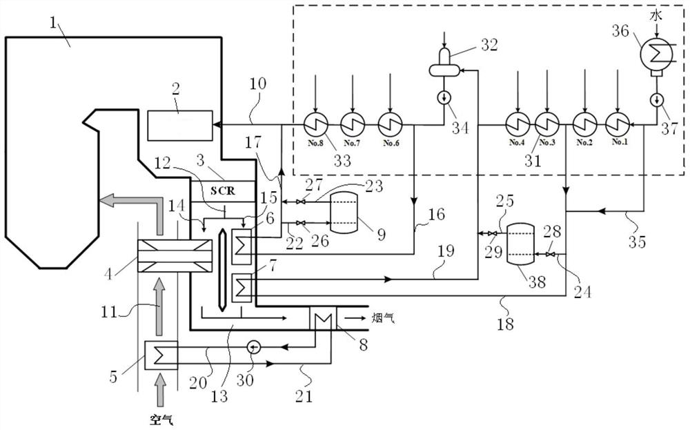
[0021] Such as figure 1 As shown, the thermal power plant flue gas waste heat recovery energy storage system in this embodiment includes a boiler 1, an economizer 2, a denitrification device 3, an air preheater 4, a high-temperature flue gas heat exchanger 6, and a medium-temperature flue gas heat exchanger device 7, high temperature water storage tank 9, low temperature water storage tank 38, water inlet main pipe 10, air intake channel 11 and smoke exhaust pipe 12, economizer 2 is installed in boiler 1, and denitrification device 3 is installed in the tailpipe of boiler 1 At 13 places, the high-temperature flue gas heat exchanger 6 and the medium-temperature flue gas heat exchanger 7 are both installed in the tailpipe 13 , and the water inlet main pipe 10 is connected to the economizer 2 to supply water to the boiler 1 . The air in...


PUM


Abstract

The invention discloses a thermal power plant flue gas waste heat recovery and energy storage system which comprises a boiler, an economizer, a denitration device, an air preheater, a high-temperature flue gas heat exchanger, a medium-temperature flue gas heat exchanger, a high-temperature water storage tank, a low-temperature water storage tank, a water inlet main pipe, an air inlet channel and a smoke exhaust pipe. The air preheater is arranged on the air inlet channel, an outlet of the smoke exhaust pipe is divided into a first smoke exhaust branch and a second smoke exhaust branch, the first smoke exhaust branch is communicated with the air preheater, and the second smoke exhaust branch is sequentially communicated with the high-temperature smoke heat exchanger and the medium-temperature smoke heat exchanger. According to the system, the high-temperature water storage tank and the low-temperature water storage tank operate to be matched with a condensation water throttling mode on the water inlet main pipe, the load lifting speed of the unit can be increased, the gradeability of the unit can be improved, safe and stable operation of the system can be maintained, and during low-load operation, the temperature of flue gas in front of an SCR denitration device is increased through storage of the high-temperature water storage tank; the removal efficiency is improved.

Description

technical field [0001] The invention relates to a technology for utilizing waste heat of flue gas of a coal-fired power plant boiler, in particular to an energy storage system for recovering waste heat of flue gas in a thermal power plant. Background technique [0002] In coal-fired power generation units, the exhaust smoke carries a large amount of available heat into the environment, which is the main heat loss of large coal-fired power plant boilers. Renewable energy power generation needs to rely on thermal power units for peak regulation and consumption. It is of great significance to improve the operational flexibility of coal-fired power units. At the same time, when coal-fired power units operate at low loads, the efficiency of SCR denitrification devices will also decrease, and the units will operate safely and stably. The ability to lift and the rate at which you can climb hills will also be reduced. In addition, the heat transfer temperature difference of the air...

Claims


Application Information

Patent Timeline
Patent Type & Authority Applications(China)
IPC IPC(8): F23J15/06F23L15/00F22D1/18F22D1/50F22D3/00F22D11/06
CPCY02E20/34
Inventor 陈珣朱光明李明曾俊蒋森年何洪浩徐曙余兴刚宾谊沅
Owner 湖南省湘电试验研究院有限公司
Learn More