


Quick Research
Generate reliable direction feasibility study reports for your R&D in just a few steps.

Technical Q&A
Discover and master advanced knowledge NOW. Basics, ideas, possibilities, all at once.

Find Solutions
As an expert in R&D theories, this can generate solutions to your technical problems instantly.

Evaluate Feasibility
Analyze your overall solution with one click, know your potential R&D risks in advance.

Monitor Landscape
Get weekly tech updates, stay abreast of the latest tech innovations and key insights.
Laminated laser spot welding method for high-strength steel
A high-strength steel and laser spot welding technology, which is applied in laser welding equipment, welding equipment, metal processing equipment, etc., can solve the problems that are difficult to meet the conditions of production and application, cannot obtain high-quality welded joints, and reduce austenite content. , to achieve the effect of reducing welding spatter, reducing weld residual stress level, and reducing absorption
- Summary
- Abstract
- Description
- Claims
- Application Information
AI Technical Summary
Problems solved by technology
Method used
Image

Examples
Embodiment 1
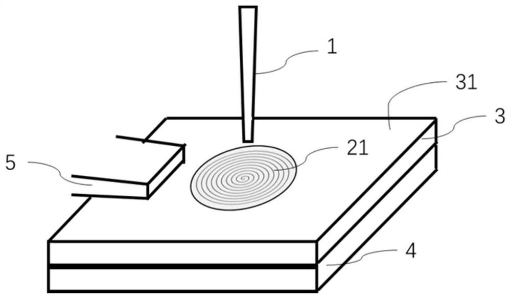
[0048] Such as figure 1 Shown is the schematic diagram of the laser spot welding process of the method of the present invention, the laser beam 1 is applied along the scanning path 21 on the first surface 31 of the stacked combination of the upper steel workpiece 3 and the lower steel workpiece 4 to form a dot-shaped weld; During this process, the compressed air generates a horizontal airflow directly above the weld seam through the air blowing port 5, blowing away the smoke and dust generated by laser welding, and ensuring that the laser beam is absorbed by the weld seam.
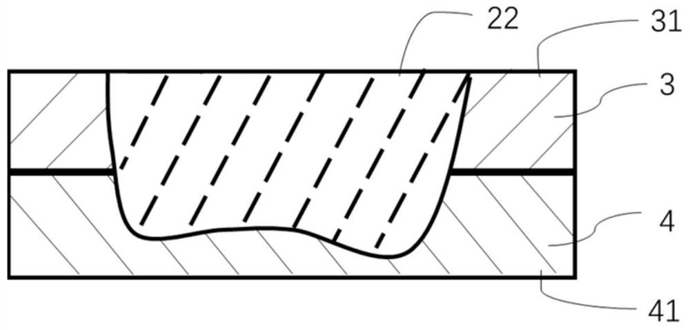
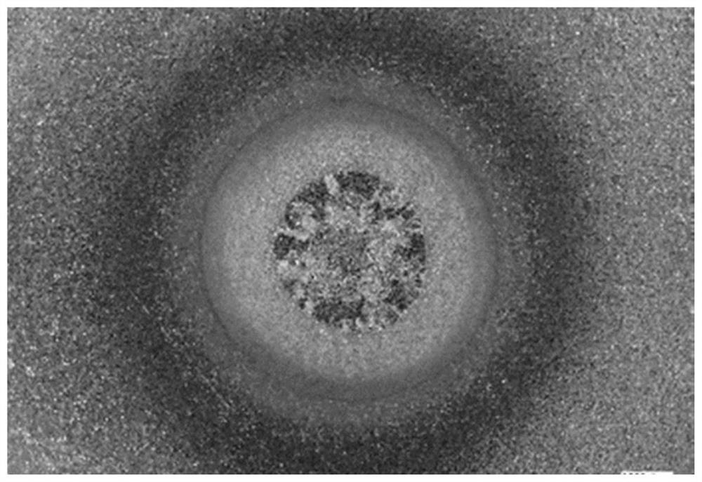
[0049] In the embodiment, the welding laminate combination is a 1.4mm QP1180 two-layer board, the scanning path 21 is a helix with 10 turns and a pitch of 0.292mm, the laser power is 2500W, and the laser beam scanning speed is 10.0m / min. figure 2 The weld seam 22 shown, ie the lower surface 41 of the lower workpiece 4 is not melted. The backside of solder joints such as image 3 As shown, the cross-sect...
Embodiment 2
[0053] Such as Figure 8 As shown, the weld seam 24 is obtained by adjusting the welding parameters. At this time, the melting area of the lower surface is about 40% of the melting area of the upper surface. Using the welding process and parameter settings in Example 1, the stacked material is combined into a QP980 two-layer board with a thickness of 1.2mm, and the laser power is set to 2300W. After the welding is completed, the back of the solder joint is as follows Figure 9 As shown, the cross-section of the solder joint is as Figure 10 As shown, the melting area of the lower surface at this time is 40% of the melting area of the upper surface.
Embodiment 3
[0055] Using the welding process and parameter settings in Example 1, the stacked material is combined into a QP980 two-layer board with a thickness of 1.0mm, and the laser power is set to 2000W. The area of the melting area on the lower surface of the obtained solder joint is 55% of the area of the upper surface melting area, which corresponds to welding The point joint tension curve is Figure 11 As shown in the invention method of Zhonghong; the laser power is 3000W, and the area of the melting area on the lower surface of the obtained solder joint is 95% of the area of the melting area on the upper surface, and the corresponding tensile curve of the solder joint is Figure 11 Shown in traditional method in blue. It can be seen that the solder joints obtained by the method of the present invention have improved joint performance, which is similar to that of QP1180 with a thickness of 1.4 mm in Example 1, and the strength and plasticity of the solder joints obtained ...
PUM
| Property | Measurement | Unit |
|---|---|---|
| tensile strength | aaaaa | aaaaa |
| thickness | aaaaa | aaaaa |
| tensile strength | aaaaa | aaaaa |
Abstract
Description
Claims
Application Information
 - R&D Engineer
- R&D Manager
- IP Professional
- Industry Leading Data Capabilities
- Powerful AI technology
- Patent DNA Extraction
Browse by: Latest US Patents, China's latest patents, Technical Efficacy Thesaurus, Application Domain, Technology Topic, Popular Technical Reports.
© 2024 PatSnap. All rights reserved.Legal|Privacy policy|Modern Slavery Act Transparency Statement|Sitemap|About US| Contact US: help@patsnap.com