Field-domain-concentrated direct-writing type micro-electrochemical machining method and field-domain-concentrated direct-writing type micro-electrochemical machining device

A micro-electrolysis and processing device technology, applied in electrochemical processing equipment, processing working medium, metal processing equipment, etc., can solve the problems of difficult to control the flow of electrolyte, reduced effective utilization of energy, low processing accuracy, etc., to improve the current Density and energy transfer, stray corrosion reduction, high capacity utilization effects

Active Publication Date: 2022-03-29
GUANGDONG POLYTECHNIC NORMAL UNIV
View PDF5 Cites 0 Cited by
  • Summary
  • Abstract
  • Description
  • Claims
  • Application Information

AI Technical Summary

Problems solved by technology

Whether it is nonlinear electrolyte or jet electrolysis, due to the fluid characteristics of the electrolyte during processing, the workpiece or the processing area will be immersed in the electrolyte. At this time, the material removal will occur in the soaked area under the influence of the electric field. Scattering corrosion leads to low processing accuracy, and the effective utilization rate of energy is reduced, the current efficiency is low, and it is difficult to achieve precision processing
Moreover, the flow of electrolyte is difficult to control. Traditional electrolyte has a corrosive effect on equipment and tooling, requiring frequent maintenance of equipment and high cost.

Method used


Image

  • Field-domain-concentrated direct-writing type micro-electrochemical machining method and field-domain-concentrated direct-writing type micro-electrochemical machining device
  • Field-domain-concentrated direct-writing type micro-electrochemical machining method and field-domain-concentrated direct-writing type micro-electrochemical machining device
  • Field-domain-concentrated direct-writing type micro-electrochemical machining method and field-domain-concentrated direct-writing type micro-electrochemical machining device

Examples


Embodiment Construction

[0040] In order for those skilled in the art to better understand the technical solution of the present invention, the present invention will be further described below in conjunction with the examples and accompanying drawings, but the embodiments of the present invention are not limited thereto.

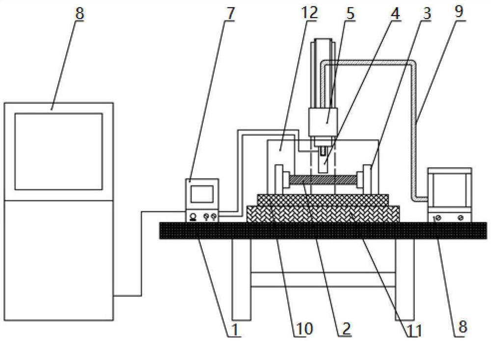
[0041] see Figure 2-4, the field-focused direct-writing micro-electrolytic machining device of this embodiment includes a workbench 1, a clamping mechanism 3 for clamping a workpiece 2, and a spindle drive mechanism for driving the tool 4 to move above the workpiece 2 5. An electrolytic medium supply mechanism 6 for supplying polymer electrolytic medium, a processing power supply 7 and an integrated control cabinet 8 .

[0042] The clamping mechanism 3 is arranged on the workbench 1. Specifically, the clamping mechanism 3 may adopt a structure in the prior art.

[0043] The electrolytic medium supply mechanism 6 includes an electrolytic medium preparation mechanism and an electro...


PUM


Abstract

The invention discloses a field-domain-concentrated direct-writing type micro-electrochemical machining method and device. The method comprises the following steps that a workpiece is clamped on a workbench through a clamping mechanism; placing the high-molecular polymer particles in an electrolytic medium preparation mechanism, and dissolving, diluting and mixing the high-molecular polymer particles by the electrolytic medium preparation mechanism to form a viscous electrolytic medium; the tail end of the conveying pipe is guided to the position above the workpiece through a position adjusting mechanism; conveying a viscous electrolytic medium to the workpiece through a conveying pipe, wherein the electrolytic medium is vertically arranged on the workpiece; driving a tool to move above the workpiece through a main shaft driving mechanism, so that the tool is inserted into the electrolytic medium; adjusting the distance between the tool and the workpiece; switching on a power supply and performing electrolytic machining on the surface of the workpiece. The high-molecular polymer material is used as a component of the electrolytic medium, the flow characteristic of the electrolyte is controlled, the concentrated corrosion capacity is improved, stray corrosion is reduced, and the direct effect of field domain concentration is achieved.

Description

technical field [0001] The invention relates to an electrolytic machining method and device, in particular to a field-focused direct-writing micro electrolytic machining method and device. Background technique [0002] Electrolytic machining is a special processing method that uses the principle of electrochemical anodic dissolution of metals in electrolytes to shape workpieces. The electrolyte flows through the gap between the electrodes, forming a conductive path between the two electrodes, and generating a current under the power supply voltage, thereby forming an electrochemical anode dissolution, and finally the gaps between the two electrodes tend to be consistent, and the surface of the workpiece is formed and the working surface of the tool basically similar shapes. [0003] The electrolytic medium in micro-electrolytic machining plays the role of participating in electrochemical reactions, dissolving materials, maintaining processing stability and taking away proce...

Claims


Application Information

Patent Timeline
Patent Type & Authority Applications(China)
IPC IPC(8): B23H3/00B23H3/08B23H3/10
CPCB23H3/00B23H3/08B23H3/10
Inventor 何俊峰周莉梁华卓王赞
Owner GUANGDONG POLYTECHNIC NORMAL UNIV
Why Eureka
Try Eureka