System and method for controlling ignition of internal combustion engine

An internal combustion engine and ignition control technology, which is applied in the direction of engine ignition, ignition energy generated by generators, spark ignition controllers, etc., can solve the problems of increasing the volume and cost of the ignition system

Inactive Publication Date: 2004-03-17
MITSUBA CORP
View PDF0 Cites 0 Cited by
  • Summary
  • Abstract
  • Description
  • Claims
  • Application Information

AI Technical Summary

Problems solved by technology

[0007] In view of this problem in the prior art, the main object of the present invention is to provide a system and method for controlling the ignition of an internal combustion engine, which can improve the ignition characteristics without increasing the volume and cost of the ignition system

Method used


Image

  • System and method for controlling ignition of internal combustion engine
  • System and method for controlling ignition of internal combustion engine
  • System and method for controlling ignition of internal combustion engine

Examples


Embodiment Construction

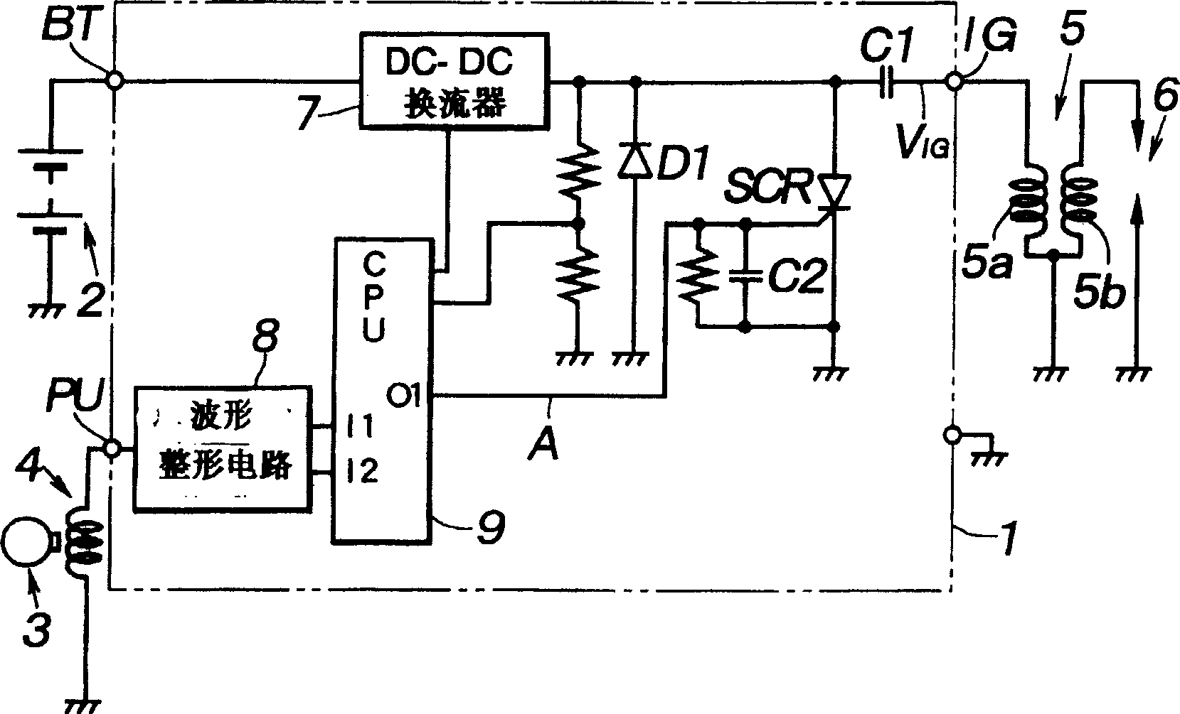
[0017] figure 1 is a circuit diagram of an ignition system for a motorcycle internal combustion engine according to the present invention. Such as figure 1 As shown, the battery 2 is connected to the voltage terminal BT of the CDI circuit 1 . The pulse generator coil 4 is connected to the pulse input terminal PU for generating a pulse-shaped ignition timing reference signal as the alternator 3 rotates, for example. The primary side coil 5 a of the ignition coil 5 is connected to the output terminal IG, and the spark plug 6 is connected to the secondary side coil 5 b of the ignition coil 5 .

[0018] In the CDI circuit 1, the DC-DC converter 7 and the main capacitor C1 are connected in series in this order on the power supply line extending from the terminal BT to the terminal IG. In addition, the main capacitor C1 is connected to the primary coil 5a of the ignition coil 5 through the terminal IG. Each ignition timing reference signal supplied to terminal PU is converted ...


PUM


Abstract

The present invention relates to a ignition control device for controlling the ignition of combustion engine. Trigger signal output from the control device(CPU)operates triggering of switching device(SCR) and controls discharge of a condenser, which is connected to primary side of an ignition coil, to carry out ignition. The invention is characterized in that the trigger signal is generated in a form of a plurality of trigger pulses, the width of each pulse is less than a discharge cycle of the condenser, so as to provide a plurality of discrete sparks separated by intervals to each ignition. Thereby the invention provides the ignition quality of continuous sparks with prolonged duration without increasing the capacity of a condenser.

Description

technical field [0001] The present invention relates to a system and method for controlling the ignition of an internal combustion engine in which a trigger signal is used to discharge a capacitor to spark a spark plug connected to the secondary side of an ignition coil. Background technique [0002] Generally speaking, some ignition systems, such as those used in motorcycle internal combustion engines, utilize the CDI system, the spark of the spark plug is generated in the form of an alternating electric arc, on which positive and negative voltages appear alternately. In this ignition system, a capacitor can be connected in series to the primary side of the ignition coil, so that the capacitor discharges through the thyristor that is turned on by a timing-controlled trigger signal. [0003] In the above-mentioned ignition system, for each ignition, an ignition signal (or trigger signal) of a predetermined duration T is generated, such as image 3 shown. From the generation...

Claims


Application Information

Patent Timeline
IPC IPC(8): F02P3/08F02P15/10
CPCF02P15/10F02P3/0846
Inventor 梁濑淳志野末裕
Owner MITSUBA CORP
Why Eureka
Try Eureka