


Quick Research
Generate reliable direction feasibility study reports for your R&D in just a few steps.

Technical Q&A
Discover and master advanced knowledge NOW. Basics, ideas, possibilities, all at once.

Find Solutions
As an expert in R&D theories, this can generate solutions to your technical problems instantly.

Evaluate Feasibility
Analyze your overall solution with one click, know your potential R&D risks in advance.

Monitor Landscape
Get weekly tech updates, stay abreast of the latest tech innovations and key insights.
Drying equipment based on commercial concrete production system
A production system and drying equipment technology, which is applied in the direction of drying solid materials, lighting and heating equipment, drying, etc., can solve the problems of concrete production impact, poor concrete drying effect, etc., to improve drying effect, facilitate drying treatment, and improve vibration effect of magnitude
- Summary
- Abstract
- Description
- Claims
- Application Information
AI Technical Summary
Problems solved by technology
Method used
Image

Examples
Embodiment 1
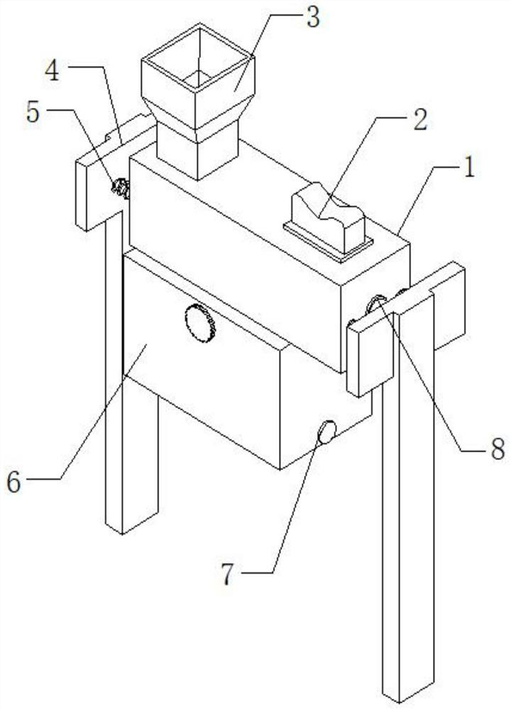
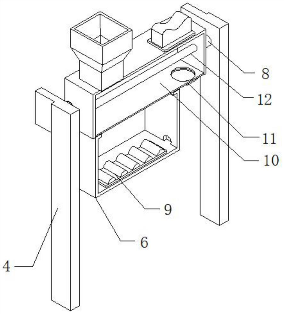
[0024] refer to Figure 1-3 , a drying equipment based on a commercial concrete production system, including a box body 1, a feed hopper 3 is arranged on one side of the top outer wall of the box body 1, a port is opened on the bottom outer wall of the box body 1, and the inner wall of the port is passed through a bolt A heat conduction plate 10 is connected, the bottom outer wall of the heat conduction plate 10 is provided with a discharge port 11, the bottom outer wall of the box body 1 is connected with a heating box 6 by bolts, and the bottom inner wall of the heating box 6 is connected with a heater 9 by bolts, the box body The outer walls on both sides of 1 are connected with springs 5 by bolts, and the outer walls of one side of spring 5 are connected with support plates 4 by bolts.
[0025] Wherein, the conveying auger 12 is rotatably connected between the inner walls on both sides of the box body 1 through bearings, and the outer wall of one side of the conveying au...
Embodiment 2
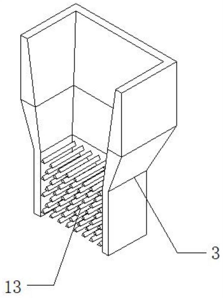
[0028] refer to Figure 1-3 , a drying equipment based on a commercial concrete production system. Compared with Embodiment 1, this embodiment has a plurality of retaining rods 13 connected by bolts between the inner walls of the opposite sides of the feed hopper 3, and the plurality of retaining rods 13 are staggered distribution, it can block the commercial concrete, so as to slow down the flow rate of commercial concrete, so as to facilitate the drying treatment of commercial concrete, prevent commercial concrete from being piled up due to the fast flow rate of commercial concrete, and thus affect the drying efficiency of commercial concrete make an impact.
[0029] Working principle: when in use, put the commercial concrete that needs to be dried into the inside of the box body 1 through the feeding hopper 3, inject an appropriate amount of water into the inside of the heating box 6 through the water inlet, start the heater 9, and then pass the heater 9 The water is heate...
PUM
 Abstract
Description
Claims
Application Information
 - R&D Engineer
- R&D Manager
- IP Professional
- Industry Leading Data Capabilities
- Powerful AI technology
- Patent DNA Extraction
Browse by: Latest US Patents, China's latest patents, Technical Efficacy Thesaurus, Application Domain, Technology Topic, Popular Technical Reports.
© 2024 PatSnap. All rights reserved.Legal|Privacy policy|Modern Slavery Act Transparency Statement|Sitemap|About US| Contact US: help@patsnap.com