Hydraulic system of cleaning and sweeping vehicle

A hydraulic system and technology for washing and sweeping cars, which is applied in the field of washing and sweeping cars, and can solve problems such as serious energy consumption of the system, system temperature rise, and changing speed

Pending Publication Date: 2022-03-25
启航汽车有限公司
View PDF0 Cites 0 Cited by
  • Summary
  • Abstract
  • Description
  • Claims
  • Application Information

AI Technical Summary

Problems solved by technology

The best sweeping effect cannot be obtained, and the speed of the sweeping plate is easily affected by the oil temperature and pressure to change the speed
When the sweeping brush rotates at the set speed, the excess oil at the outlet of the hydraulic pump will flow back to the oil tank from the overflow valve and the throttle valve, which will cause serious energy consumption in the system, and the excess energy will be converted into heat energy, causing the system to heat up and easily Affect system reliability
At present, the cleaning vehicle is not equipped with a pressure monitoring device. Whether there is any abnormality during the cleaning process cannot be known at the first time, which will easily cause waste of resources and damage to components.
[0004] As mentioned above, the actual road pollution levels of different road sections are different, and the optimal sweeping speed and pressure required are also different. Traditional sweeping vehicles cannot adjust the optimal sweeping speed and pressure according to different road conditions to obtain the best cleaning speed. Excellent sweeping effect; and the traditional sweeping car consumes a lot of energy

Method used


Image

  • Hydraulic system of cleaning and sweeping vehicle
  • Hydraulic system of cleaning and sweeping vehicle
  • Hydraulic system of cleaning and sweeping vehicle

Examples


no. 1 example

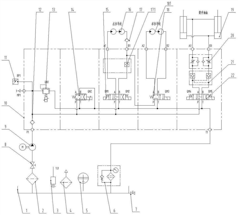
[0033] [First Embodiment] A hydraulic system for washing and sweeping vehicles, such as figure 1 , 2As shown, it includes an integrated hydraulic oil tank 1; an oil pump 9; at least one sweeping motor, which is used to drive the brush; a valve group 10, which is used to adjust the pressure and speed of the sweeping motor; a pressure sensor 11. The pressure sensor 11 is used to monitor the working pressure of the hydraulic system; among them, the integrated hydraulic oil tank 1, the oil pump 9, the valve group 10, the sweeping motor, and the pressure sensor 11 are connected through the oil circuit.

[0034] In the above embodiments, the integrated hydraulic oil tank 1 is an oil tank for storing hydraulic oil, and hydraulic oil is an important medium flowing in the oil circuit, and the hydraulic oil is transported in the oil circuit to realize the purpose of controlling the hydraulic system. The oil pump 9 is a single gear oil pump 9, the price is relatively cheap, it can save ...

no. 3 example

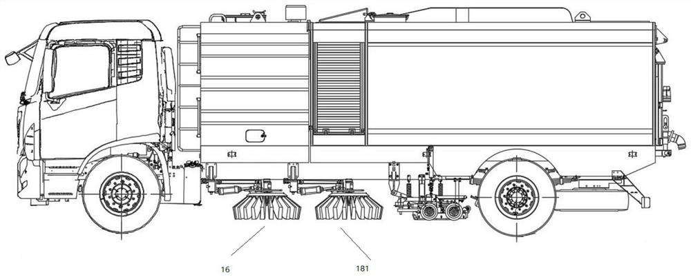
[0038] [Third embodiment] if figure 1 , 2 As shown, the panning motors include a left panning motor 16 and a right panning motor 181 .

[0039] In the above embodiment, there are preferably two sweeping motors, which are specifically arranged on the lower surface of the middle part of the car body. The left sweeping motor 16 controls a row of left sweeping brushes, and the right sweeping motor 181 controls a row of right sweeping brushes. disk, the rotation direction of the left pan motor 16 and the right pan motor 181 is fixed. Garbage can be swept into the box in the sweeper.

[0040] [Fourth Embodiment] If figure 1 , 3 , 4, the valve group 10 includes: a first one-way valve 12, the first one-way valve 12 is used to control the flow direction of hydraulic oil in the oil circuit; Set different set current values; proportional directional valve 14, proportional directional valve 14 sets different set voltage values ​​under different working conditions; valve block, valve ...


PUM


Abstract

The invention provides a cleaning and sweeping vehicle hydraulic system which comprises an integrated hydraulic oil tank. An oil pump; the sweeping disc motor is used for driving the sweeping brush; the valve group is used for adjusting the pressure and the speed when the sweeping disc motor works; the pressure sensor is used for monitoring the working pressure when the hydraulic system works; wherein the integrated hydraulic oil tank, the oil pump, the valve group, the sweeping disc motor and the pressure sensor are connected through an oil path. According to different road conditions, different set current values of the proportional overflow valve and different set voltage values of the proportional reversing valve are set, so that the working rotating speed and working pressure of the sweeping disc motor in different road working states are met.

Description

technical field [0001] The invention relates to the technical field of cleaning and sweeping vehicles, in particular to a hydraulic system for cleaning and sweeping vehicles. Background technique [0002] The sweeper is a vehicle used to clean up garbage on the road. There is a box for accommodating garbage in the sweeper, and the garbage on the road is cleaned by sweeping. Therefore, the speed and pressure of the sweeper depend on the degree of road pollution and the degree of garbage. The greater the particle size and density of the road pollution, the greater the particle size and density of the garbage, the greater the required sweeping speed and pressure, but too high a sweeping speed will cause excessive dust, and too high a sweeping pressure will Seriously affect the life of the hydraulic motor and waste of energy consumption. Therefore, in order to obtain the best brushing effect, it is necessary to adjust the speed and pressure of the brushing according to the road...

Claims


Application Information

Patent Timeline
Patent Type & Authority Applications(China)
IPC IPC(8): F15B11/08F15B13/02F15B13/01F15B19/00F15B21/041
CPCF15B11/08F15B13/02F15B13/01F15B19/00F15B21/041
Inventor 杨广生许月平高枘沈董董王建嵇佳文
Owner 启航汽车有限公司
Why Eureka
Try Eureka