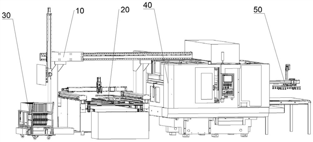
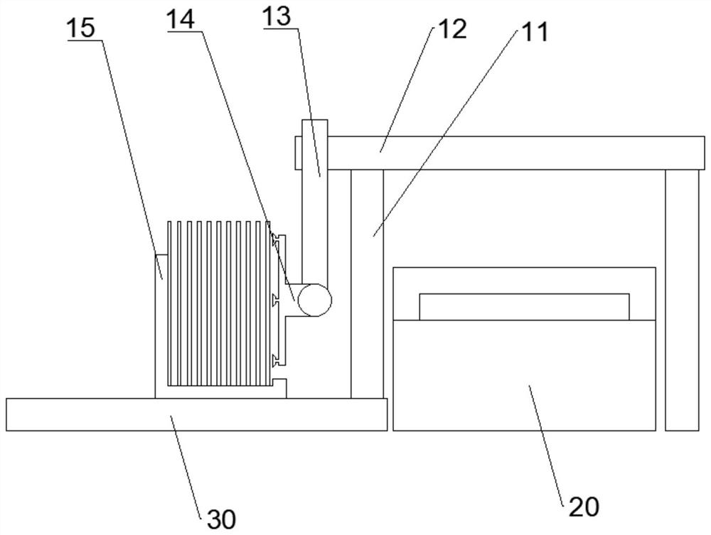
Glass processing production line

A production line and glass technology, applied in glass manufacturing equipment, glass cutting devices, manufacturing tools, etc., can solve the problems of glass cutting arms, high labor costs, and limited internal and external space, so as to speed up material transportation and reduce preprocessing steps , Improve the effect of transfer efficiency

Pending Publication Date: 2022-03-25
广东科杰技术股份有限公司
View PDF0 Cites 1 Cited by
  • Summary
  • Abstract
  • Description
  • Claims
  • Application Information

AI Technical Summary

Problems solved by technology

Glass processing usually adopts the method of stacking material racks to place the glass next to the automatic glass cutting machine platform. When the glass automatic cutting machine platform needs glass, at least two workers are required to operate at the same time to transport the entire piece of glass to the automatic glass cutting machine platform. At the entrance, the glass is only manually moved, and the loading of the glass automatic cutting machine platform has a large workload and low efficiency. The glass has the risk of cutting the arm, and the labor cost is relatively high.
[0004] Therefore, large glass with a large area needs to be transported by rollers during the production process. In the process of glass production, an automatic feeding unit will be used. This automatic feeding unit is used in conjunction with the mechanical arm and the suction cup. Adsorb the glass to complete the effect of feeding, but the mechanical arm in the mechanical arm structure needs to be rotated multiple times to adjust the direction of the glass, grasping and rotating multiple times to complete the transfer operation of the glass plate, which requires high positioning of the mechanical arm , the process is cumbersome and requires a large space
Moreover, due to the limitation of the internal and external space of the casing of the CNC unit, the swing door is used. This kind of door structure is inconvenient to use, and it is difficult to cooperate with the mechanical arm feeding unit, and the flexibility is not good.

Method used


Image

  • Glass processing production line
  • Glass processing production line
  • Glass processing production line

Examples


Embodiment Construction

[0047] The following are specific embodiments of the present invention and in conjunction with the accompanying drawings, the technical solutions of the present invention are further described, but the present invention is not limited to these embodiments.

[0048] In describing the present invention, it should be understood that the terms "center", "longitudinal", "transverse", "upper", "lower", "front", "rear", "left", "right", " The orientations or positional relationships indicated by "vertical", "horizontal", "top", "bottom", "inner" and "outer" are based on the orientations or positional relationships shown in the drawings, and are only for the convenience of describing the present invention and Simplified descriptions, rather than indicating or implying that the referred unit or element must have a specific orientation, be constructed and operate in a specific orientation, and therefore should not be construed as limiting the invention.

[0049] It should be noted that ...


PUM


Abstract

The invention relates to a glass processing production line. The glass processing production line comprises a feeding unit, a cutting and breaking unit and a CNC processing unit which are arranged in sequence, the feeding unit comprises a feeding rack, a first moving arm, a second moving arm and a glass adsorption mechanism; the glass adsorption mechanism is used for adsorbing to-be-processed glass from the glass conveying mechanism, and the first moving arm and the second moving arm are used for driving the glass adsorption mechanism to move from the glass conveying mechanism to the cutting and breaking-off unit or move from the cutting and breaking-off unit to the CNC processing unit; the CNC machining unit is provided with a sealing shell, and the side wall of the feeding side of the sealing shell is provided with a transverse glass feeding port and an operation channel used for operation of the second moving arm. According to the glass processing production line, manual intervention of middle procedures is reduced, and automation of the whole process from feeding to discharging after processing of large-size glass is achieved.

Description

technical field [0001] The invention relates to the technical field of glass processing, in particular to a glass processing production line. Background technique [0002] Glass is an amorphous inorganic non-metallic material. It is generally made of a variety of inorganic minerals as the main raw material and a small amount of auxiliary raw materials. Its main components are silicon dioxide and other oxides, and the main component is silicate double salt. It is an amorphous solid with irregular structure and is widely used in daily life. [0003] Glass flakes are usually made by cutting and grinding glass, and its silicon dioxide content can reach more than 99.99%. The hardness is Mohs seven, and it has the characteristics of high temperature resistance, low thermal expansion coefficient, thermal shock resistance and good electrical insulation performance. Glass sheets are widely used in the market, and are mostly used to produce window glass, automotive glass, electronic...

Claims


Application Information

Patent Timeline
Patent Type & Authority Applications(China)
IPC IPC(8): C03B33/03C03B33/033C03B33/037B65G49/06
CPCC03B33/03C03B33/033C03B33/037B65G49/062B65G49/064B65G49/061
Inventor 周振财陈福更曾伟强王正宁梁思琪
Owner 广东科杰技术股份有限公司
Why Eureka
Try Eureka