Turning anti-deformation bidirectional structure and method based on edge long overhanging thin wall

An anti-deformation and overhang technology, used in turning equipment, metal processing equipment, manufacturing tools, etc., can solve the problems of no positioning surface support, uncontrollable turning deformation, and no axial bidirectional movement, achieving light weight, Optimized clamping layout, simple and compact structure

Pending Publication Date: 2022-03-25
JINCHENG NANJING ELECTROMECHANICAL HYDRAULIC PRESSURE ENG RES CENT AVIATION IND OF CHINA
View PDF0 Cites 0 Cited by
  • Summary
  • Abstract
  • Description
  • Claims
  • Application Information

AI Technical Summary

Problems solved by technology

In addition, the center of rotation of thin-walled parts is used for positioning and pressing, which will cause long overhangs on the edges and thick walls, and there is no positioning surface support.
It can be seen that for the turning surface with long overhanging wall thickness, the clamping force and supporting surface cannot be effectively applied to the workpiece during clamping, and the deformation caused by turning processing cannot be controlled; the positioning surface is opposite to the processing surface, and the supporting edge The secondary positioning surface with long overhanging wall thickness can not be adjusted, and there is no axial bidirectional movement effect due to the influence of structural space

Method used


Image

  • Turning anti-deformation bidirectional structure and method based on edge long overhanging thin wall
  • Turning anti-deformation bidirectional structure and method based on edge long overhanging thin wall
  • Turning anti-deformation bidirectional structure and method based on edge long overhanging thin wall

Examples


Embodiment

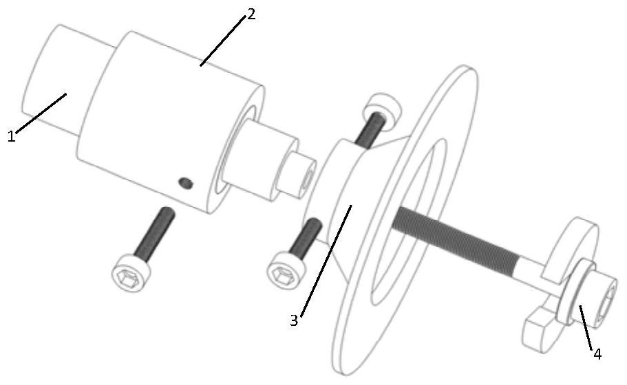
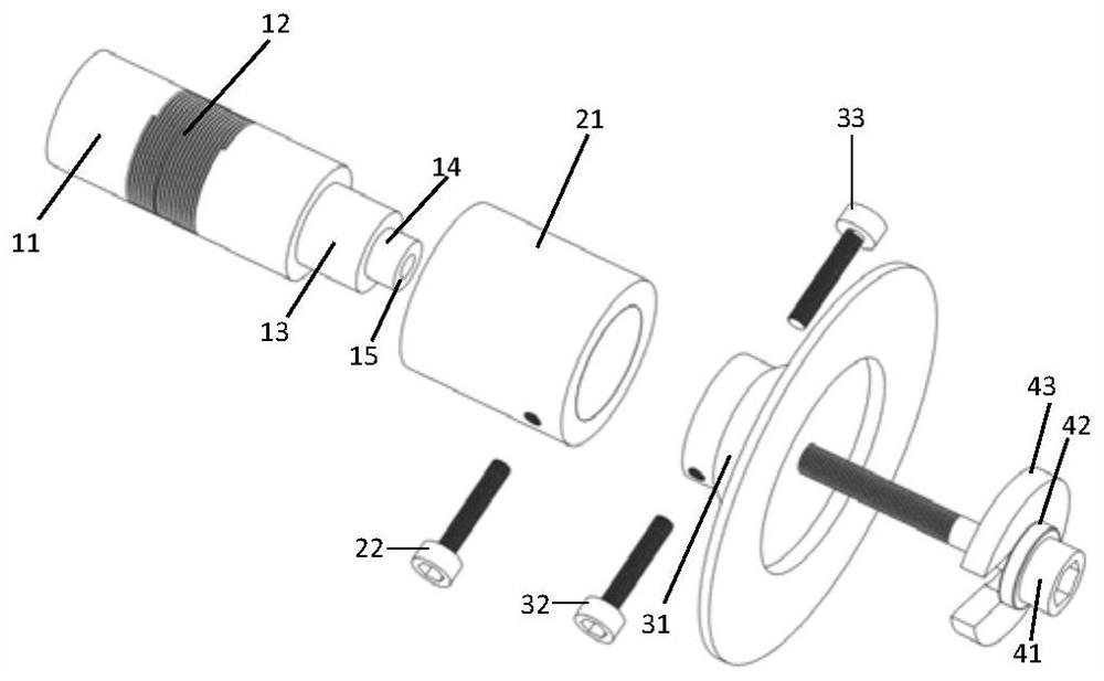
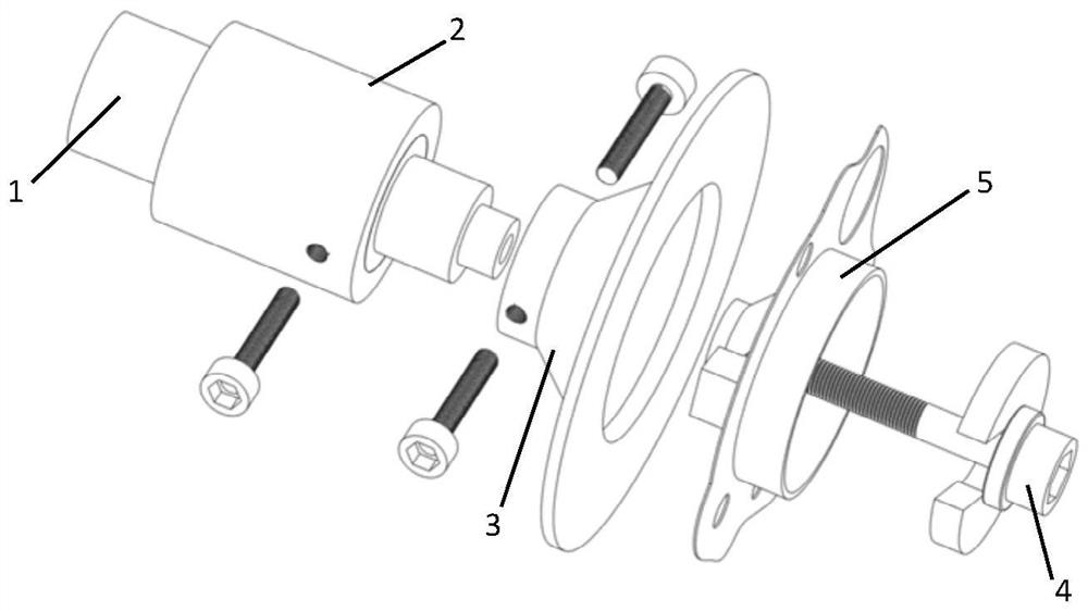
[0036] Embodiment: A preferred embodiment of the present invention is provided below. The structure of thin-walled parts with long overhangs on the edge: the center part of the gyratory has a sleeve-like end face and an end face with thin and elongated edges, showing a cantilevered state.

[0037] First, open the three-jaw chuck of the main shaft of the turning lathe, expand the size slightly larger than the size of the chuck shaft 11 of the base 1, and stuff it into the chuck shaft 11, so that the three-jaw chuck can not lose it, and then use Use a dial gauge to calibrate the workpiece positioning shaft 14 of the base 1 to no more than 0.01 and tighten the three claws; put on the thrust bushing 21 to expose the entire sliding shaft 13 and screw on the A locking screw 22; install the secondary positioning disc 3 on the sliding shaft 13, Install the B locking screw 32 and the C locking screw 33 on both sides at the same time; the clamping 4 is threadedly connected to the thread...


PUM


Abstract

The invention belongs to the field of machine manufacturing and light alloy machining deformation, and relates to a turning machining anti-deformation bidirectional structure and method based on an edge long overhanging thin wall, the structure comprises a base, a locking shaft sleeve, a secondary positioning disc and a clamping structure, the base sequentially penetrates through the locking shaft sleeve and the secondary positioning disc to be connected with the clamping structure, and the locking shaft sleeve is connected with the clamping structure; on the basis of maintaining the original clamping of the edge long overhanging thin-wall part, a supporting effect of a suspended secondary contact surface of the machined thin-wall part is provided, a complete fitting effect is achieved, the free state and the machining process state of the thin-wall part are kept consistent, an axial two-way operation function is achieved, two-way positioning and two-way pressing are achieved, and the machining precision of the thin-wall part is improved. And the pressing force has no distributed internal stress effect on the edge long overhanging wall thickness. The device has the advantages of being simple and compact in structure, light in weight, high in efficiency and high in precision, deformation in the turning process of the thin-wall part is controlled through optimization of clamping force and clamping layout, machining quality is guaranteed, and the device has important actual guiding value.

Description

technical field [0001] The invention belongs to the field of mechanical manufacturing and light alloy processing deformation, and specifically relates to a two-way anti-deformation structure and method for turning a thin wall with long overhang at the edge, aiming at the two-way effect of the free state and the clamping state of the thin wall with long overhang on the edge before and after turning. Structural action realizes controllable deformation of parts. Background technique [0002] Due to the inherent weak rigidity of thin-walled parts, the clamping force and cutting force during the cutting process are prone to "cutting" and clamping deformation, which leads to substandard machining accuracy. For the aerospace field, light-weight and high-strength thin-walled parts are mostly used, and the technical requirements such as high processing accuracy and surface quality are used to ensure their service cycle performance and reliability. At the same time, the processing qu...

Claims


Application Information

Patent Timeline
IPC IPC(8): B23B31/103B23B25/06
CPCB23B31/103B23B25/06
Inventor 袁维东刘伟徐庆军沈广亮王双孙贺龙何明发郎旭东
Owner JINCHENG NANJING ELECTROMECHANICAL HYDRAULIC PRESSURE ENG RES CENT AVIATION IND OF CHINA
Why Eureka
Try Eureka