
Waterproof structure of box culvert deformation joint

A technology of waterproof structure and deformation joints, which is applied in the field of deformation joints, can solve problems such as leakage in box culverts, reduce the probability of leakage, and enhance the effect of anti-seepage

Active Publication Date: 2022-03-18
江苏雷威建设工程有限公司
View PDF6 Cites 2 Cited by
  • Summary
  • Abstract
  • Description
  • Claims
  • Application Information

AI Technical Summary

Problems solved by technology

[0005] In order to improve the problem of easy leakage between two box culverts, this application provides a waterproof structure for deformation joints of box culverts

Method used


Image

  • Waterproof structure of box culvert deformation joint
  • Waterproof structure of box culvert deformation joint
  • Waterproof structure of box culvert deformation joint

Examples


Embodiment 1

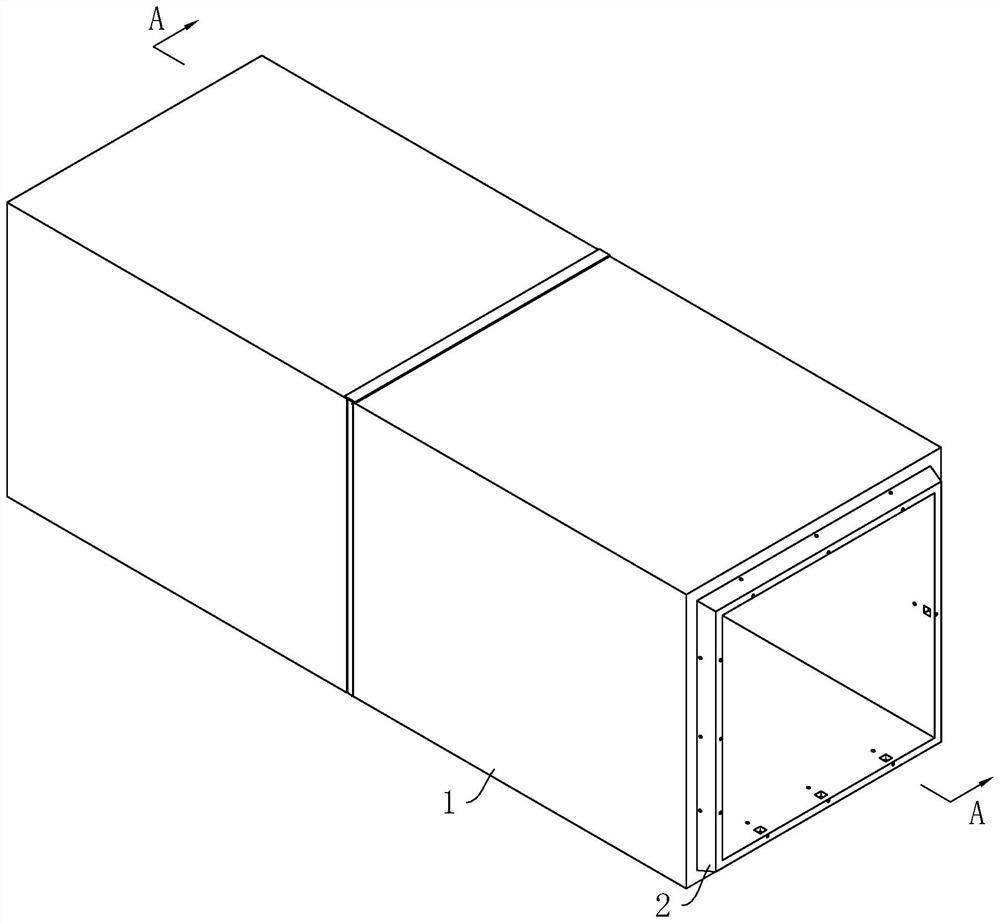
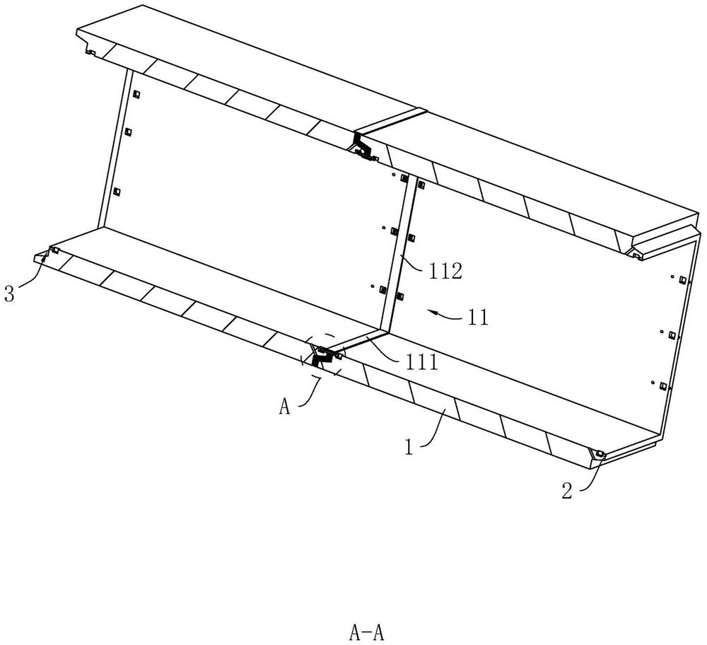
[0043] refer to figure 1 , the waterproof structure of the deformation joint of the box culvert includes several box culverts 1. In this embodiment, the number of box culverts 1 is two as an example, and one side end wall of one box culvert 1 is provided with a box for extending into another box culvert. The positioning ring block 2 in 1, the positioning ring block 2 is integrally formed with the box culvert 1, and the other side end wall of the box culvert 1 is provided with a positioning ring groove 3 matching with the positioning ring block 2, and the positioning ring groove 3 It is connected with the port of box culvert 1. During construction, the two box culverts 1 are docked by means of oil cylinder jacking, until the positioning ring block 2 is inserted into the positioning ring groove 3, so as to realize the butt joint assembly between the two box culverts 1 .

[0044] refer to figure 2 with image 3 , in this embodiment, the outer ring wall of the positioning ring...

Embodiment 2

[0053] refer to Figure 4 with Figure 5 The difference between the embodiment of the present application and embodiment 1 lies in the structure of the connection assembly 10 .

[0054] refer to Image 6 with Figure 7 , the connecting assembly 10 includes two connecting plates 12, the length of the connecting plates 12 is consistent with the length or width or height of the box culvert 1, the connecting plate 12 in the present embodiment is made of waterproof material, and two adjacent box culverts 1 Connection grooves 13 are provided on the inner side walls of the two connection grooves 13, and the two connection plates 12 correspond to the two connection grooves 13 respectively. The connecting port 14 connected to the space 4, one side of the connecting plate 12 passes through the connecting port 14 and extends into the impermeable space 4, the two connecting plates 12 are arranged opposite each other, and one of the connecting plates 12 is located on the end wall of the...


PUM


Abstract

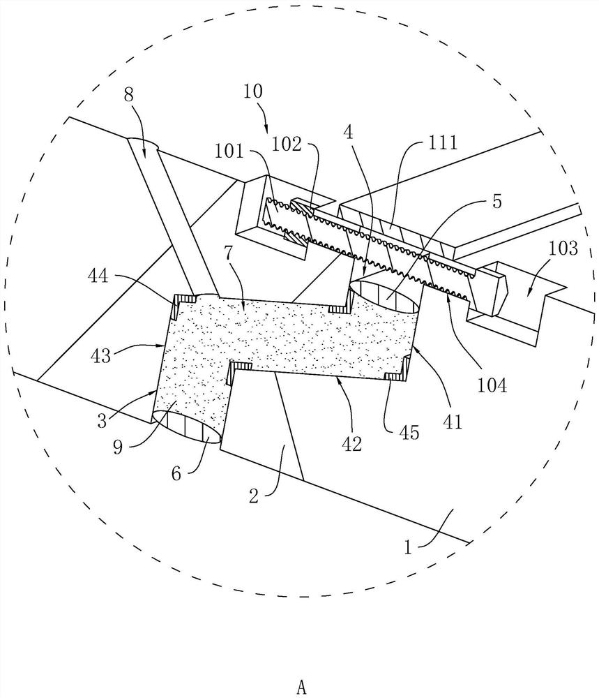
The invention relates to a waterproof structure of a box culvert deformation joint, and belongs to the field of deformation joints, the waterproof structure comprises a plurality of box culverts, an inner sealing ring and an outer sealing ring, the end wall of one box culvert is provided with a positioning ring block, and the end wall of the other box culvert is provided with a positioning ring groove allowing the positioning ring block to be inserted therein; an anti-seepage space is defined between the side wall of the positioning ring block and the groove wall of the positioning ring groove, the inner sealing ring and the outer sealing ring are both arranged in the anti-seepage space, a grouting space is defined by the inner sealing ring, the outer sealing ring, the positioning ring block and the groove wall of the positioning ring groove, and a plurality of grouting holes communicating with the grouting space are formed in the inner side wall of the box culvert. A grouting waterproof layer is arranged in the grouting space, the inner side walls of every two adjacent box culverts are connected through a connecting assembly, and the side walls of the box culverts are provided with sealing assemblies used for blocking the openings of the anti-seepage spaces. The method has the effect of reducing the probability of leakage between the two box culverts.

Description

technical field [0001] The present application relates to the field of deformation joints, in particular to a waterproof structure for deformation joints of box culverts. Background technique [0002] Deformation joints are the general term for expansion joints, settlement joints and seismic joints. Buildings are often deformed under the action of external factors, resulting in cracking or even destruction. Deformation seams are structural seams reserved for this situation. [0003] In the related technology, the urban underground pipe gallery is generally composed of several box culverts. The box culverts are prefabricated in advance. During the process, a deformation joint will be reserved between two adjacent box culverts, and the sealant connection between two adjacent box culverts will be realized by filling the sealant in the deformation joint. [0004] In view of the related technologies mentioned above, the inventor believes that there are the following defects: t...

Claims


Application Information

Patent Timeline
Patent Type & Authority Applications(China)
IPC IPC(8): E02D29/045E02D29/16
CPCE02D29/045E02D29/16E02D29/10
Inventor 樊夏敏钱涛张建中曹红权夏智华
Owner 江苏雷威建设工程有限公司
Learn More