Thermal Insulation System for Non-Vacuum Applications Including a Multilayer Composite

a multi-layer composite and thermal insulation technology, applied in the field of thermal insulation systems and methods of insulating in non-vacuum applications, can solve the problems of long life expectancy of thermal insulation systems and notoriously difficult management of conventional insulation systems around pipe supports, and achieves cost-effective, convenient use, and simple installation

Active Publication Date: 2014-09-11
NASA
View PDF2 Cites 17 Cited by
  • Summary
  • Abstract
  • Description
  • Claims
  • Application Information

AI Technical Summary

Benefits of technology

The present invention is a thermal insulation system that is designed for non-vacuum applications in the ambient pressure environment. The system includes a multilayered composite with at least one thermal insulation layer and at least one compressible barrier layer that work together for optimal thermal performance, mechanical operations, and prevention of moisture intrusion and corrosion. The system is breathable, meaning it allows for the natural draining of water vapor, and can be installed easily and quickly. It is cost-effective, reliable, and can be used in a wide range of commercial and industrial products. The system is also mechanically robust and can withstand impact, vibration, and heavy equipment. It can be modified, cut, or trimmed without degrading in mechanical performance. The system provides superior thermal insulation performance compared to polyurethane foam systems and is more cost-effective.

Problems solved by technology

The thermal insulation system has a long life expectancy because all layers are hydrophobic or otherwise waterproof.
Conventional insulation systems are notoriously difficult to manage around pipe supports due to the cracking and damage that can occur.

Method used


Image

  • Thermal Insulation System for Non-Vacuum Applications Including a Multilayer Composite
  • Thermal Insulation System for Non-Vacuum Applications Including a Multilayer Composite
  • Thermal Insulation System for Non-Vacuum Applications Including a Multilayer Composite

Examples


Embodiment Construction

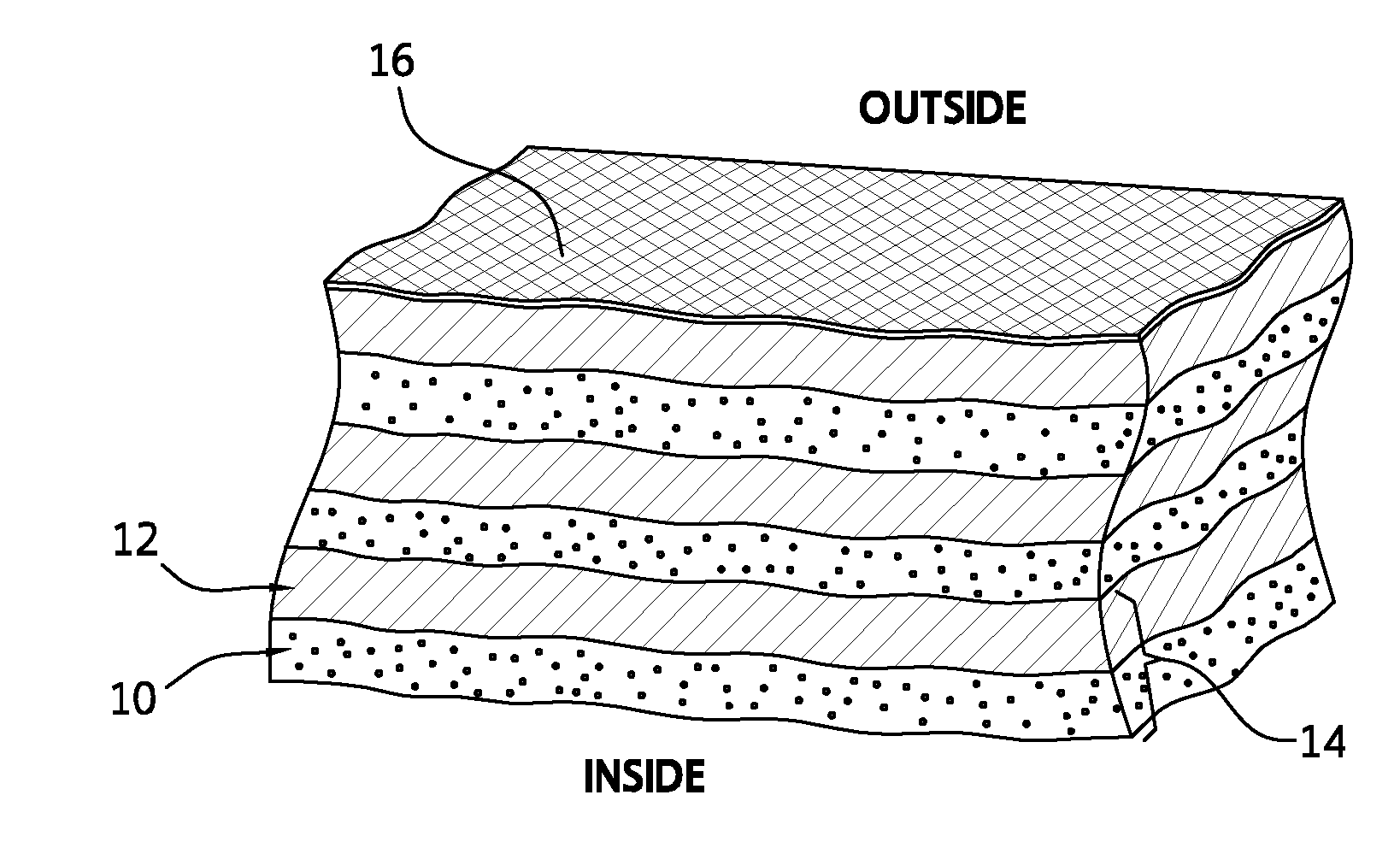
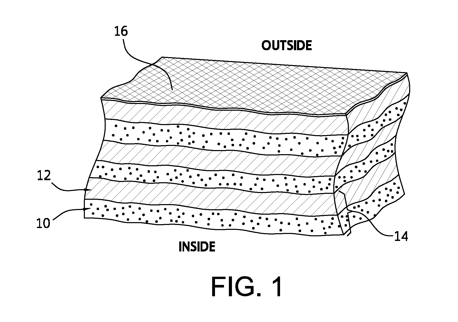
[0050]The present thermal insulation system is an externally applied system for non-vacuum applications which comprises a) a multilayered composite having an inner surface and an outer surface and b) an optional outer casing surrounding the outer surface of the multilayered composite. As provided in FIG. 1, the multilayered composite includes i) at least one thermal insulation layer 10 and at least one compressible barrier layer 12 provided as alternating, successive layers and ii) at least one reflective film provided on at least one surface of said compressible barrier layer and / or thermal insulation layer. Both thermal insulation layer(s) and compressible barrier layer(s) are conformable to a three-dimensional surface of an article to be insulated. The thermal insulation layer 10 is always disposed directly adjacent to the surface of the article to be insulated. The reflective film is formed of a material selected from a group consisting of metal foils and metalized foils. In one...


PUM

PropertyMeasurementUnit
compressiveaaaaaaaaaa
pressuresaaaaaaaaaa
pressuresaaaaaaaaaa

Abstract

The thermal insulation system of the present invention is for non-vacuum applications and is specifically tailored to the ambient pressure environment with any level of humidity or moisture. The thermal insulation system includes a multilayered composite including i) at least one thermal insulation layer and at least one compressible barrier layer provided as alternating, successive layers, and ii) at least one reflective film provided on at least one surface of the thermal insulation layer and / or said compressible barrier layer. The different layers and materials and their combinations are designed to provide low effective thermal conductivity for the system by managing all modes of heat transfer. The thermal insulation system includes an optional outer casing surrounding the multilayered composite. The thermal insulation system is particularly suited for use in any sub-ambient temperature environment where moisture or its adverse effects are a concern. The thermal insulation system provides physical resilience against damaging mechanical effects including compression, flexure, impact, vibration, and thermal expansion / contraction.

Description

CROSS-REFERENCE TO RELATED APPLICATIONS[0001]This application claims the benefit, under 35 U.S.C. 119(e), of U.S. Provisional Application No. 61 / 776,639 filed Mar. 11, 2013, the contents of which are incorporated herein by reference.ORIGIN OF THE INVENTION[0002]The invention described herein was made by an employee of the United States Government and may be manufactured and used by or for the Government of the United States of America for governmental purposes without the payment of any royalties thereon or therefore.BACKGROUND OF THE INVENTION[0003]1. Field of the Invention[0004]The present invention relates generally to a thermal insulation system and method of insulating in non-vacuum applications.[0005]2. Description of Related Art[0006]It is often necessary or desirable to limit heat transfer from an object to its surroundings. Heat transfer is the transfer of energy resulting from a temperature differential between the object and its surroundings. Heat transfer occurs through ...

Claims


Application Information

Patent Timeline
Patent Type & Authority Applications(United States)
IPC IPC(8): B65D90/06F16L59/16
CPCB65D90/06E04B2001/7691F16L59/022F16L59/184F16L59/08F16L59/161F16L59/029B32B15/046B32B15/20B32B27/065B32B2266/0278B32B2307/304B32B2307/416B32B2307/712B32B2307/7265B65D90/022Y10T156/10Y10T428/13Y10T428/233Y10T428/239Y10T428/24999Y10T428/31678
Inventor FESMIRE, JAMES E.
Owner NASA
Why Eureka
Try Eureka