
Electronic expansion valve and manufacturing method thereof

An electronic expansion valve, technology of manufacturing method, applied in the direction of valve operation/release device, lift valve, valve details, etc., can solve the problems of unreliable sealing, increased leakage at threaded joints, high defect rate, etc.

Active Publication Date: 2015-01-21
ZHEJIANG SANHUA CLIMATE & APPLIANCE CONTROLS GRP CO LTD
View PDF5 Cites 16 Cited by
  • Summary
  • Abstract
  • Description
  • Claims
  • Application Information

AI Technical Summary

Problems solved by technology

In the mass assembly process, reliable sealing cannot be guaranteed, and the defect rate of external leakage is high
Moreover, due to the transportation turnover process, vibration during use, and corrosion and oxidation, the leakage at the threaded connection will increase sharply with the increase in service life
[0007] Second, using threaded connection, in order to ensure the strength of the connection part, the design thickness and weight of the material must be increased, resulting in higher product cost

Method used


Image

  • Electronic expansion valve and manufacturing method thereof
  • Electronic expansion valve and manufacturing method thereof
  • Electronic expansion valve and manufacturing method thereof

Examples


Embodiment Construction

[0096] In order to enable those skilled in the art to better understand the technical solutions of the present invention, the present invention will be further described in detail below with reference to the accompanying drawings and specific embodiments.

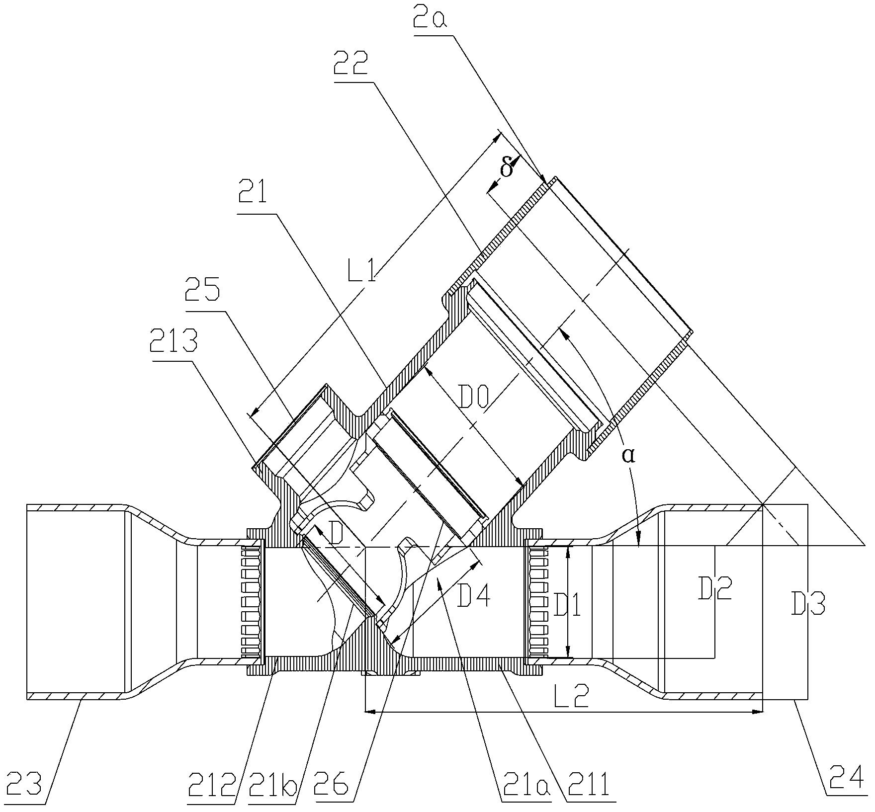
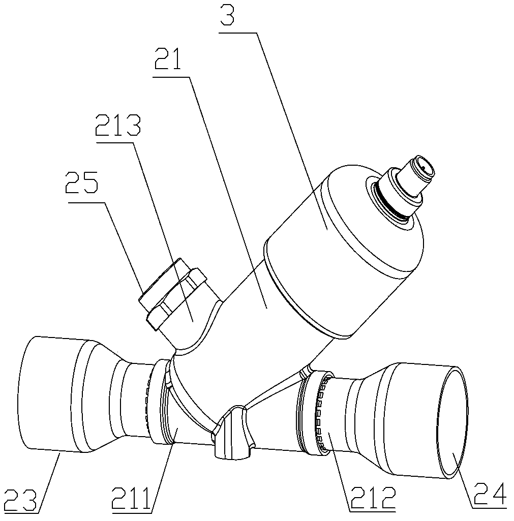
[0097] Please refer to Figure 2-4 , figure 2 It is a schematic structural diagram of a specific embodiment of the valve seat assembly of the electronic expansion valve provided by the present invention; image 3 For having figure 2 Schematic diagram of the electronic expansion valve of the middle valve seat assembly; Figure 4 for image 3 Axial sectional view of the electronic expansion valve in the middle.

[0098] The electronic expansion valve in this embodiment includes a housing part 3 and a valve seat assembly. The valve seat assembly includes a first connecting pipe 24 and a second connecting pipe 23 that are substantially in the same straight line. The valve seat assembly is provided with a first connecting pipe 24 and...


PUM

PropertyMeasurementUnit
Angleaaaaaaaaaa

Abstract

The invention discloses an electronic expansion valve and a manufacturing method thereof. The electronic expansion valve comprises a shell component and a valve seat assembly. The valve seat assembly comprises a first connecting pipe and a second connecting pipe which are located on the same straight line. A main valve cavity is formed by the valve seat assembly, an included angle of the acute angle is formed by the main valve cavity and the first connecting pipe, the valve seat assembly is of an integral structure and is fixedly connected with the shell component through welding, and the preset distance is reserved between the radial extending line of the welding position of the valve seat assembly and the shell component and the first connecting pipe. According to the electronic expansion valve, due to the fact that the preset distance is reserved between the radial extending line of the welding position and the first connecting pipe, when a valve body rotates relatively to carry out welding, the welding can be smoothly carried out without the obstruction of the first connecting pipe, and the integrated valve body is formed. Compared with a thread connecting mode in the background technology, the electronic expansion valve is of an integral structure, and the leakage rate of products can be obviously reduced; meanwhile, the thickness of materials does not need to be increased, the quality of the materials does not need to be improved, and the production cost of the products can be effectively controlled.

Description

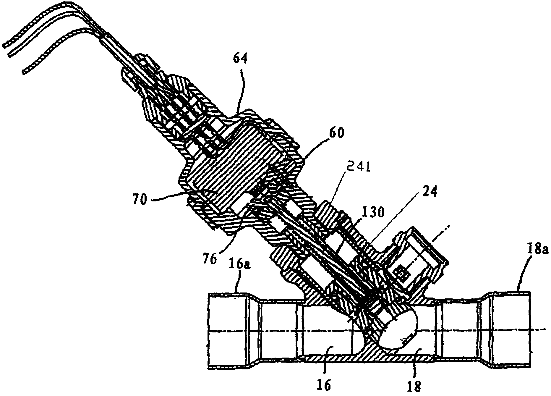
Technical field [0001] The invention relates to the technical field of valve bodies, in particular to an electronic expansion valve and a manufacturing method thereof. Background technique [0002] Please refer to figure 1 , figure 1 It is a schematic diagram of a typical electronic expansion valve. [0003] The electronic expansion valve includes a valve seat assembly, a housing member 64, and a valve stem assembly 130. The valve seat assembly includes a valve seat 24 and a cover 60. The lower end of the valve seat 24 is provided with a first interface 18 and a second interface 16 opposite to each other to connect the first connection pipe 18a and the second connection pipe 16a, the first connection pipe 18a and the second connection pipe 16a is in the same straight line. The valve seat 24 forms a main valve cavity, and the main valve cavity and the first connecting pipe 18a have an acute angle, that is, the valve seat 24 is in a "Bu" shape. [0004] The motor 70 of the electroni...

Claims


Application Information

Patent Timeline
IPC IPC(8): F16K27/00F16K31/00
CPCF16K1/42F16K27/102F25B41/31F25B41/34Y02B30/70
Inventor 不公告发明人
Owner ZHEJIANG SANHUA CLIMATE & APPLIANCE CONTROLS GRP CO LTD
Learn More