
Polishing pad

A polishing pad and polishing layer technology, which is applied in the field of polishing pads, can solve problems such as performance degradation, recovery performance degradation, and uneven grinding rate, and achieve high yield, small fluctuations, and stable manufacturing processes.

Active Publication Date: 2022-03-18
HUBEI DINGHUI MICROELECTRONICS MATERIALS CO LTD +1
View PDF11 Cites 0 Cited by
  • Summary
  • Abstract
  • Description
  • Claims
  • Application Information

AI Technical Summary

Problems solved by technology

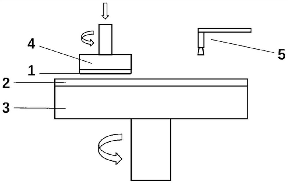
[0005] In the prior art, the buffer layer often has a soft and elastic structure. Such an elastic structure enables the buffer layer to act as a buffer and support during the polishing process. During long-term use, the buffer layer is repeatedly compressed and recovered, which will cause The decline in performance is mainly due to the internal heat generated by the sliding at the molecular level during the compression and recovery process, resulting in a decrease in recovery performance. This is mainly manifested in polishing as the life cycle (lifetime) prolongs and the edge position is removed. The edge profile has an obvious deterioration trend, which eventually leads to an increase in the non-uniformity (NU) of the grinding rate, that is, a decrease in planarization performance.

Method used


Image

  • Polishing pad
  • Polishing pad
  • Polishing pad

Examples


preparation example Construction

[0049] The preparation method of the above polyurethane resin is as follows: put the polyfunctional isocyanate into a 1L three-necked bottle, increase the reaction temperature to 70°C to 90°C within 30 to 60 minutes, and after the polyfunctional isocyanate is completely melted, start the agitator, and the stirring speed 300-500 rpm. The first polyol is dissolved and added dropwise to the polyfunctional isocyanate, and the dropping time is controlled within 1.5-3 hours. After the dropwise addition is complete, add the catalyst, continue the heat preservation reaction at 80°C to 110°C for 2 to 5 hours, and then perform defoaming treatment on the reactant, and control the vacuum degree of defoaming to -0.096MPa, 80°C, 60 minutes , to obtain a prepolymer, the free -NCO mass percentage is 6.5-9.6%; add a chain extender and a solvent to the above-mentioned prepolymer, mix well, and react at 80°C for 200min-300min to obtain a polyurethane resin The solution, after removing the solve...

Embodiment

[0104] The present invention will be further described below with reference to the schematic examples shown in the accompanying drawings. Through the following description, the advantages of various aspects of the present invention will be more obvious. In the accompanying drawings, the same reference numerals refer to the same components. In the schematic drawings The shape and size of each component are for illustration only, and cannot be recognized as reflecting the actual shape, size and absolute position.

[0105] DMF: N,N-dimethylformamide;

[0106] MDI: diphenylmethane diisocyanate;

[0107] TDI: toluene diisocyanate;

[0108] PU: foamed polyurethane;

Synthetic example 1

[0109] Polyurethane resin synthesis example 1-A1

[0110] Put 6 parts by mass of TDI and 17.5 parts by mass of MDI into a 1L three-necked flask, raise the reaction temperature to 70°C within 30 minutes, and after the TDI and MDI are completely melted, start the stirrer at a stirring speed of 300 rpm. After dissolving 57 parts by mass of polyester polyol Kurapol P-2010 and 3.4 parts by mass of polyether polyol PPG3000, they were added dropwise to TDI and MDI, and the dropping time was controlled at 1.5 hours. After the dropwise addition is completed, add 0.005 parts by mass of dibutyltin dilaurate, continue to keep warm at 80°C for 2 hours, and then perform defoaming treatment on the reactant. , 60 minutes, to obtain the prepolymer, its free -NCO mass percentage is 7.5%; add 6.2 mass parts of 1,4-butanediol and 47 mass parts of DMF to the above prepolymer, after mixing uniformly, React at 80°C for 200 minutes to obtain the desired polyurethane resin solution, and then remove t...


PUM

PropertyMeasurementUnit
Densityaaaaaaaaaa
Thicknessaaaaaaaaaa
Densityaaaaaaaaaa

Abstract

The invention relates to a polishing pad, in which the ratio of the restoring force Ft of a buffer layer in the polishing pad at the moment t of a stress relaxation stage after pressure F0 is applied to the applied pressure F0 and t meet the fitting relationship in the following formula (1), 0 < = t < = 30s, a and b are constants and meet the following conditions: 0.01 < = a < = 0.1 and / or 1.0 < = b < = 1.1, the goodness of fit R2 of the formula (1) is greater than or equal to 0.95, and the sum of the values of the formula (1) is greater than or equal to 0.95. According to the polishing pad prepared from the buffer layer meeting the fitting relation, the removal rate curve and the edge removal rate are kept stable in the whole life cycle of the polishing pad, fluctuation is small, the grinding rate non-uniformity NU value is low, and fluctuation is small. F (t) = Ft / F0 =-a * ln (t) + b (1).

Description

technical field [0001] The invention relates to the technical field of chemical mechanical planarization polishing, in particular to a polishing pad. Background technique [0002] With the development of the feature size of integrated circuits towards the deep nanometer process, the feature size is getting smaller and smaller, and the defects caused by the CMP process become more and more prominent in the advanced process, and even reach the level that seriously affects the performance of the chip. . For this reason, as one of the four core materials of the CMP process, the pursuit of the ultimate performance of the polishing pad is an eternal topic in the research and development of the polishing pad. For the performance indicators of polishing pads, the ultimate stability and uniformity have gained more and more consensus in the CMP field. The requirements for the stability and uniformity of polishing pads are gradually improved from the stability and uniformity of macro...

Claims


Application Information

Patent Timeline
IPC IPC(8): B24B37/22B24B37/10B24B37/24
CPCB24B37/22B24B37/107B24B37/24
Inventor 罗乙杰张季平高越刘敏
Owner HUBEI DINGHUI MICROELECTRONICS MATERIALS CO LTD
Learn More