Thermal jet natural gas hydrate exploitation device, system and method

A natural gas and hydrate technology, which is applied in the fields of mining fluids, drilling equipment and methods, earthwork drilling, etc., can solve the problems of limited heating mining range, low energy efficiency, environmental pollution, etc., to ensure continuity and stability, Avoid freezing and clogging, high mining efficiency

Pending Publication Date: 2022-03-08
CHINA PETROLEUM & CHEM CORP +1
View PDF0 Cites 0 Cited by
  • Summary
  • Abstract
  • Description
  • Claims
  • Application Information

AI Technical Summary

Problems solved by technology

The main disadvantages of this method are low energy efficiency, large investment, and limited coverage of heating exploitation, and it is difficult to avoid the collapse problem during the development of shallow seabed gas hydrate
[0005] The high input cost of injecting chemical reagents, environmental pollution and other issues strictly limit the application of this technology; the development technology of injecting supercritical carbon dioxide is still lack of theoretical demonstration, and the acquisition, storage and cost of supercritical carbon dioxide also restrict this technology Applications
[0006] In addition, there is fracturing technology in the field of conventional oil and gas development. Since it cannot form stable fractures in non-diagenetic formations, this technology is also not suitable for the development of non-diagenetic natural gas hydrate in shallow oceans.
[0007] Therefore, there is still no method to realize the efficient development of shallow seabed gas hydrate

Method used


Image

  • Thermal jet natural gas hydrate exploitation device, system and method

Examples


Embodiment 1

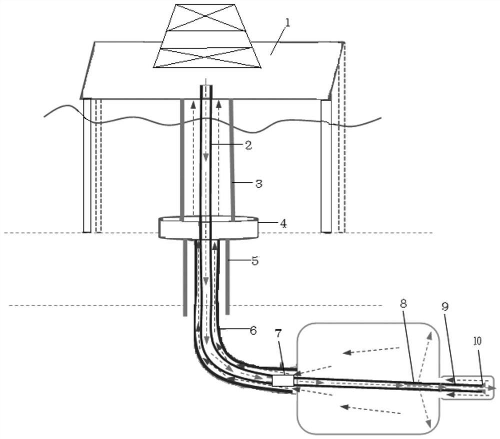
[0038] like figure 1 As shown, the present invention provides a thermal jet natural gas hydrate extraction device, which includes a coiled tube 2 capable of rotating and drilling in the natural gas hydrate layer. When the coiled tube 2 is rotating, it sprays hot water outward to form a thermal jet for Exploitation of natural gas hydrate by jet fracture.

[0039] The thermal jet natural gas hydrate extraction device in the present invention combines thermal development and high-pressure jet flow on the coiled pipe 2 capable of continuous rotary drilling in the natural gas hydrate layer, and adopts the form of jet fracture mining for natural gas hydrate, Effectively realize the development of natural gas hydrate in shallow non-diagenetic formations in the ocean.

[0040] By forming a stable rotating thermal jet, the natural gas hydrate can be effectively cracked, the natural gas hydrate contained in the non-diagenetic formation can be cracked and decomposed, and the hot water c...

Embodiment 2

[0043] In this embodiment, the outside of the coiled tubing 2 is provided with a casing 6, and the end of the casing 6 is an open structure. The coiled tubing 2 extends from the end of the casing 6 and enters the natural gas hydrate layer. Out of the coiled tubing 2 outside the casing 6, the jet is sprayed outward to form a rotating thermal jet that can effectively crack the natural gas hydrate.

[0044]After the gas hydrate layer is decomposed by the rotating thermal jet, a fluid mixture composed of hot water, broken formation particles, gas hydrate debris and part of natural gas can be obtained. The annulus gap between the holes is flowed back to the offshore platform for follow-up treatment; while in the original formation, a fractured cavity will be formed, and the three-dimensional space of the cavity is specifically centered on the continuous tube 2, which is horizontally distributed in the natural gas hydration zone. In the material layer, as the coiled tubing 2 continu...

Embodiment 3

[0049] The coiled tubing 2 in this embodiment is provided with a drilling tool 7, and the coiled tubing 2 connected downstream of the drilling tool 7 protrudes from the casing 6, and rotates and directional drills in the natural gas hydrate layer.

[0050] Specifically, the drilling tool 7 divides the coiled tubing 2 into a non-rotating section and a rotating section driven by the drilling tool 7. The rotating section of the coiled tubing 2 protrudes from the casing 6 and is continuously rotated and oriented under the action of the drilling tool 7. drilled into.

[0051] In the initial stage of the production operation, the installation position of the drilling tool 7 should at least ensure that the rotating section is outside the casing 6, and the natural gas hydrate layer downstream of the end of the casing 6 is exploited; in the subsequent production process, the non-rotating section And the drilling tool 7 can gradually protrude from the casing 6 during the running of the ...


PUM


Abstract

The invention discloses a thermal jet natural gas hydrate mining device, system and method, the mining device comprises a continuous pipe capable of rotatably drilling in a natural gas hydrate layer, the continuous pipe sprays hot water outwards during rotation to form thermal jet, and the thermal jet is used for performing jet cracking mining on natural gas hydrate; a casing pipe is arranged outside the continuous pipe, the continuous pipe extends out of an opening in the tail end of the casing pipe to enter a natural gas hydrate layer, and hot water carries the natural gas hydrate subjected to injection cracking decomposition to flow back and be recycled through an annular gap between the casing pipe and the continuous pipe. Hot water is used for replacing conventional drilling fluid, a drilling tool is used for driving the continuous pipe to rotate, stable rotating thermal jet flow is formed, a larger swept area can be obtained, and the exploitation amount is increased; meanwhile, guiding and logging tools are installed at the tail end of the continuous pipe, the drilling direction of the continuous pipe is controlled in real time, rotary drilling of the continuous pipe in the natural gas hydrate layer all the time is effectively achieved, and the high recovery rate is kept in the mining process.

Description

technical field [0001] The invention relates to the technical field of natural gas hydrate development, in particular to a thermal jet natural gas hydrate exploitation device, system and method. Background technique [0002] my country's demand for clean energy keeps growing at a high speed, but my country's dependence on foreign oil and natural gas resources is getting higher and higher, seriously affecting my country's energy security. Natural gas hydrate reserves are abundant in my country. Experts estimate that natural gas hydrate reserves are twice the current coal and oil reserves combined, and my country has successfully drilled combustible ice in the Shenhu sea area and the Qilian Mountain permafrost. 1m 3 Combustible ice can produce 164m 3 methane, and the combustion product CO 2 and H 2 O, belongs to high calorific value, clean and pollution-free green energy. [0003] Theoretically, there are two ideas for the development of natural gas hydrates: one is the s...

Claims


Application Information

Patent Timeline
IPC IPC(8): E21B43/01E21B43/24E21B47/00E21B7/06
CPCE21B43/01E21B43/24E21B7/064E21B47/00
Inventor 张文平曾义金陈武君谷磊尹慧博魏辽程光明张瑞
Owner CHINA PETROLEUM & CHEM CORP
Why Eureka
Try Eureka