Eureka AIR delivers breakthrough ideas for toughest innovation challenges, trusted by R&D personnel around the world.

Corrugated board column-to-column die cutting machine

A technology of corrugated cardboard and round pressing, which is applied in the field of corrugated cardboard round pressing and round die-cutting machines, can solve the problems of waste and leftover material penetration, high labor intensity of personnel, and difficult processing work, so as to avoid the safety of personnel and the environment, and reduce the Labor intensity, the effect of ensuring accuracy

Inactive Publication Date: 2022-03-04
谢佳慧
View PDF0 Cites 0 Cited by
  • Summary
  • Abstract
  • Description
  • Claims
  • Application Information

AI Technical Summary

Problems solved by technology

[0006] Aiming at the deficiencies of the prior art, the present invention provides a corrugated cardboard circular die-cutting machine, which solves the problem that the waste and leftovers of the existing corrugated cardboard circular die-cutting machine usually penetrate into the equipment, and the long-term processing It will block the equipment and cause equipment damage. At the same time, it requires personnel to feed materials continuously for a long time. The labor intensity of personnel is high, and it is difficult to maintain long-term processing work.

Method used


Image

  • Corrugated board column-to-column die cutting machine
  • Corrugated board column-to-column die cutting machine
  • Corrugated board column-to-column die cutting machine

Examples


Embodiment 1

[0039] see Figure 1-3 , the present invention provides a technical solution: a corrugated cardboard rotary die-cutting machine, specifically comprising:

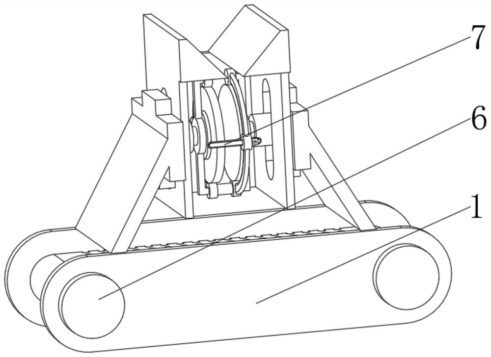
[0040] Support frame 1, the support frame 1 has a round end plate body, and a protective bottom plate 2 installed in the middle of the bottom of the inner cavity of the round end plate, and a T-shaped dust suction fan 3 installed on the top of the protective bottom plate 2, and a T-shaped dust suction fan 3 installed on the round end The rotating shaft 4 on both sides of the inner cavity of the plate, the feeding belt 5 installed on the outer surface of the rotating shaft 4, and the drive motor 6 installed on the outside of the round end plate body and at the position of the rotating shaft 4, and installed on the top of the round end plate body The circular die-cutting device 7 can absorb the airflow through the design of the T-shaped dust suction fan 3, and the strong negative air pressure can collect the powder generated ...

Embodiment 2

[0047] see Figure 1-4 On the basis of Embodiment 1, the present invention provides a technical solution: the die-cutting device 77 includes:

[0048] Rotating motor 771, this rotating motor 771 has cylindrical main body, and is installed in cylindrical main body away from the rotating connecting plate 772 of electric telescoping rod 76 side, and is installed in rotating connecting plate 772 and is away from the circular pressing plate 773 of cylindrical main body side, and is installed in The auxiliary rod 774 on both sides of the outer surface of the cylindrical main body, and the fitting guide wheel 775 that is installed on the auxiliary rod 774 away from the end of the cylindrical main body, and the semicircle mounting rod 776 that is installed on the outer surface of the fitting guide wheel 775, and is installed on the semicircle mounting rod The cutting device 777 in the middle position of 776 is installed on the pressure switch 778 that is located at the front of the ci...

Embodiment 3

[0053] see Figure 1-6 , on the basis of Embodiment 1 and Embodiment 2, the present invention provides a technical solution: the cutting device 777 includes:

[0054] Positioning column 7771, the positioning column 7771 has a cylinder, and an L-shaped fixed frame 7772 installed on the top of the cylinder, and a lifting driver 7773 installed on the top of the L-shaped fixed frame 7772, and a rod-shaped rod installed in the middle of the lifting driver 7773 Cutter 7774. Through the design of the lifting driver 7773, the processing distance of the rod cutter 7774 can be adjusted, which is suitable for die-cutting of corrugated cardboard with different thicknesses. At the same time, the distance adjustment of the rod cutter 7774 assists the blade of the rod cutter 7774 to loosen , to avoid the occurrence of cutting jamming.

[0055] One end of the rod-shaped cutter 7774 away from the lifting driver 7773 runs through the positioning column 7771 and extends to the side of the posi...


PUM


Abstract

The invention discloses a corrugated board column-to-column die-cutting machine which specifically comprises a supporting frame, a T-shaped dust collection fan installed on the top of a protective bottom plate and a column-to-column die-cutting device installed on the top of a round end plate body, and the column-to-column die-cutting device comprises an installation frame and a lifter installed on the top of a splayed frame body. The position adjusting frame plate is installed on the side, away from the splayed frame body, of the lifter, the guide block is installed on the top of the position adjusting frame plate, the electric telescopic rod is installed in an inner cavity of a penetrating groove, and the die cutting device is installed at the end, away from the position adjusting frame plate, of the electric telescopic rod. The invention relates to the technical field of corrugated boards. Corrugated boards needing to be subjected to die cutting machining can be stacked through the guide blocks and the position adjusting frame plate, continuous manual material supply is avoided, the labor intensity of workers is reduced, meanwhile, excessive corrugated boards can be prevented from entering the die cutting device through position adjustment, and the machining accuracy of equipment is ensured.

Description

technical field [0001] The invention relates to the technical field of corrugated cardboard, in particular to a circular die-cutting machine for corrugated cardboard. Background technique [0002] Corrugated cardboard is made of surface paper, inner paper, core paper and corrugated corrugated paper processed into corrugated corrugated paper. It is a kind of board, generally divided into two types: single corrugated cardboard and double corrugated cardboard. Corrugated cartons are widely used. , has the advantages of low cost, light weight, easy processing, high strength, excellent printing adaptability, convenient storage and transportation, etc. More than 80% of corrugated paper can be recycled and recycled. Corrugated paper can be used as packaging for food or digital products, which is relatively environmentally friendly , is more widely used. [0003] In the production process of corrugated cardboard boxes, it is necessary to use a rotary die-cutting machine to cut the ...

Claims


Application Information

Patent Timeline
Patent Type & Authority Applications(China)
IPC IPC(8): B31B50/06B31B50/20B31B50/74B31B50/94B31B50/00B26D7/18
CPCB31B50/06B31B50/20B31B50/94B31B50/74B31B50/006B26D7/1863
Inventor 谢佳慧
Owner 谢佳慧
Why Eureka
Eureka Blog
Learn More