Clamping-adjustable automobile annular part mounting platform and mounting method
A technology of ring-shaped parts and installation platform, applied in the field of automobile parts processing, can solve the problems of process interruption, difficult metal processing post-processing, low industrial processing efficiency, etc., to achieve the effect of improving processing efficiency, improving continuity, and facilitating blanking
- Summary
- Abstract
- Description
- Claims
- Application Information
AI Technical Summary
Problems solved by technology
Method used
Image

Examples
Embodiment 1
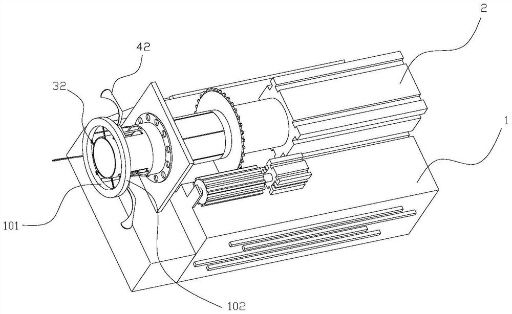
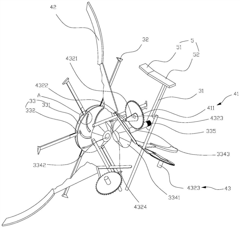
[0076] Such as Figure 1-3 As shown, this embodiment discloses a clamping and adjustable mounting platform for automotive ring parts, including a mounting base 1, a telescopic device 2, an inner clamping follower 31, an inner support clamping block 32, an inner clamping drive mechanism 33, The outer clamp follower 41 , the outer pressure clamp rod 42 , the outer clamp drive mechanism 43 , the inner ring brake part 5 , and the outer ring brake part 6 . The telescopic device 2 is installed on the mounting base 1 . The inner clamping follower 31 , the inner clamping driving mechanism 33 , the outer clamping follower 41 , and the outer clamping driving mechanism 43 are all arranged on the telescopic end of the telescoping device 2 .
[0077]During the stretching process of the telescopic end of the telescopic device 2 from back to front, as the contact time between the inner clamping follower 31 and the inner ring brake 5 continues, the inner clamping follower 31 can change from ...
Embodiment 2
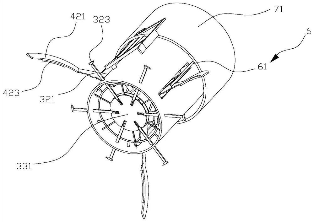
[0118] Such as image 3 , 11 As shown, the difference between this embodiment and the above-mentioned embodiments is that it further includes a limiting sleeve 71, and the limiting sleeve 71 is sleeved on the periphery of the telescopic end. On the inner wall of the limit sleeve 71, a limit chute 711 for front and rear guidance is provided, and a slide bar 214 is provided on the surface of the telescopic end, and the slide bar 214 extends into the limit chute 711 to slidably cooperate with the limit chute 711. Both the inner ring brake part 5 and the outer ring brake part 6 are fixed on the limit sleeve 71 .
[0119] The structure of the spacer sleeve 71 of the present invention and its cooperation with the telescopic end can provide points for the installation of the inner ring brake 5 and the outer ring brake 6 on the one hand, and ensure that the telescopic end moves forward and backward without the spacer sleeve 71 is relatively immobile; on the other hand, it is possibl...
Embodiment 3
[0121] Such as Figure 17-19 As shown, the difference between the present embodiment and the above-mentioned embodiments is that the inner ring braking member 5 includes a horizontal section 52 and an inclined section 51 in sequence from back to front. The terminal end of the horizontal section 52 is connected to the starting end of the inclined section 51 . The pressing surface of the horizontal section 52 is parallel to the central axis of the telescopic track of the telescoping end (that is, the pressing surface of the horizontal section 52 in this embodiment is of constant height), and the pressing surface of the inclined section 51 is from back to front to match the central axis of the telescopic end. The distance between the horizontal planes of the axis gradually increases to its terminal end. In this embodiment, the height of the pressing surface of the inclined section 51 gradually increases from the rear to the front.
[0122] During the stretching movement of the t...
PUM
 Abstract
Description
Claims
Application Information
 - R&D
- Intellectual Property
- Life Sciences
- Materials
- Tech Scout
- Unparalleled Data Quality
- Higher Quality Content
- 60% Fewer Hallucinations
Browse by: Latest US Patents, China's latest patents, Technical Efficacy Thesaurus, Application Domain, Technology Topic, Popular Technical Reports.
© 2025 PatSnap. All rights reserved.Legal|Privacy policy|Modern Slavery Act Transparency Statement|Sitemap|About US| Contact US: help@patsnap.com