Metal ceramic tube shell package for low-frequency high-power device

A technology of high-power devices and metal ceramics, which is applied to electric solid-state devices, semiconductor devices, and semiconductor/solid-state device components, etc., can solve the problems of poor heat dissipation, cracking of the ceramic body of the packaging tube and shell, and burning of power chips, etc. Avoid overheating and burn damage, improve rapid heat dissipation, and avoid cracking

Pending Publication Date: 2022-03-01
THE 13TH RES INST OF CHINA ELECTRONICS TECH GRP CORP
View PDF0 Cites 0 Cited by
  • Summary
  • Abstract
  • Description
  • Claims
  • Application Information

AI Technical Summary

Problems solved by technology

At present, the aspect ratio of package tubes used in high-power devices is close to four to one. At the same time, since the method of adhesive fixing cannot meet the long-term use requirements, in order to ensure long-term sealing performance, most power device packages are fixed by brazing. However, due to the poor ductility of the solder, when fixing the package case in practical engineering applications, due to the pulling of the fastening stress, it is easy to cause the ceramic body of the package case to crack, and in severe cases, it may even cause damage to the power chip and burn it. In addition, due to the high calorific value of high-power devices, the heat dissipation effect of relying solely on the package shell itself to dissipate heat toward the outside is poor, which is also a factor that causes power chips to overheat and burn out and affect their long-term reliability.

Method used


Image

  • Metal ceramic tube shell package for low-frequency high-power device
  • Metal ceramic tube shell package for low-frequency high-power device
  • Metal ceramic tube shell package for low-frequency high-power device

Examples


Embodiment Construction

[0022] In order to make the technical problems, technical solutions and beneficial effects to be solved by the present invention clearer, the present invention will be further described in detail below in conjunction with the accompanying drawings and embodiments. It should be understood that the specific embodiments described here are only used to explain the present invention, not to limit the present invention.

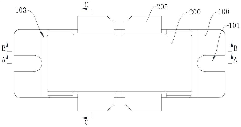
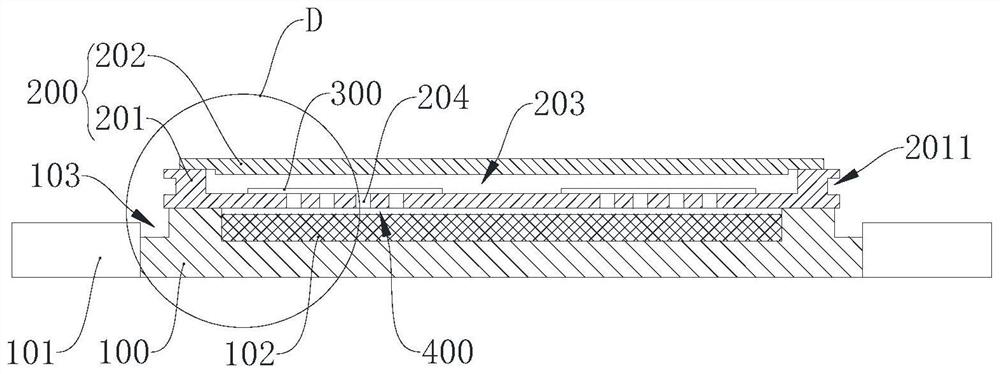
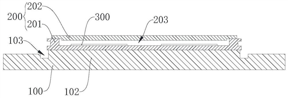
[0023] Please also refer to Figure 1 to Figure 4 , a metal-ceramic package for a low-frequency high-power device provided by the present invention will now be described. The metal-ceramic package of low-frequency and high-power devices includes a rectangular metal heat sink 100, a ceramic package body 200, and a power device 300; two ends of the metal heat sink 100 are respectively provided with connecting parts 101, and the metal heat sink The top surface of 100 is embedded with a thermal phase change material layer 102 between the two connecting parts 101; the ...


PUM


Abstract

The invention provides a metal ceramic tube shell package for a low-frequency high-power device. The metal ceramic tube shell package comprises a quasi-rectangular metal heat sink, a ceramic package body and a power device, the two ends of the metal heat sink are respectively provided with a connecting part, and a thermal phase change material layer is embedded between the two connecting parts; a first heat dissipation part is arranged on the bottom wall of the ceramic packaging body, and the first heat dissipation part corresponds to the phase change material layer in position; the power device is attached to the inner bottom wall of the ceramic packaging body and located over the first heat dissipation part. Wherein the first heat dissipation part is used for conducting heat dissipated by the power device to the thermal phase change material layer, and then the heat is transferred to the metal heat sink for heat exchange with the outside; the metal heat sink is provided with a stress slow-release part in a region between the ceramic packaging body and the two connecting parts. According to the low-frequency high-power device metal ceramic tube shell package provided by the invention, the long-term use reliability of the power device can be improved in two aspects of overcoming the mechanical stress problem and the heat dissipation problem.

Description

technical field [0001] The invention belongs to the technical field of tube and shell packaging, and in particular relates to a metal ceramic tube and shell package for low-frequency and high-power devices. Background technique [0002] With the development of microwave power devices towards high power, the power chips used in the devices are getting larger and larger, so the aspect ratio of the package shell is also increasing, which leads to the stress problem of power devices in engineering applications getting more serious. At present, the aspect ratio of package tubes used in high-power devices is close to four to one. At the same time, because the adhesive fixing method cannot meet the long-term use requirements, in order to ensure long-term sealing performance, most power device packages are fixed by brazing. However, due to the poor ductility of the solder, when fixing the package case in practical engineering applications, due to the pulling of the fastening stress...

Claims


Application Information

Patent Timeline
IPC IPC(8): H01L23/427H01L23/367H01L23/373H01L23/00
CPCH01L23/562H01L23/427H01L23/3736H01L23/367
Inventor 高永辉徐守利银军夏达顾颖言蔡晓波张晓帆赵景波默江辉翟岐段雪杨光晖
Owner THE 13TH RES INST OF CHINA ELECTRONICS TECH GRP CORP
Why Eureka
Try Eureka