
Ejector pin mechanism and crystal ejection equipment

A technology of thimble and thimble sleeves, which is applied in the direction of electrical components, semiconductor/solid-state device manufacturing, circuits, etc., can solve the problems of inconvenient operation process of thimble pin replacement and affect the replacement efficiency, and achieve the effect of easy replacement and high efficiency

Active Publication Date: 2022-03-01
SHENZHEN XINYICHANG TECH CO LTD
View PDF11 Cites 1 Cited by
  • Summary
  • Abstract
  • Description
  • Claims
  • Application Information

AI Technical Summary

Problems solved by technology

[0004] The purpose of the embodiment of the present application is to provide an ejector pin mechanism and crystal ejector equipment to solve the problem in the related art that the operation process of ejector ejector pin replacement is relatively inconvenient and affects the replacement efficiency

Method used


Image

  • Ejector pin mechanism and crystal ejection equipment
  • Ejector pin mechanism and crystal ejection equipment
  • Ejector pin mechanism and crystal ejection equipment

Examples


Embodiment Construction

[0048] In order to make the technical problems, technical solutions and beneficial effects to be solved by the present application clearer, the present application will be further described in detail below in conjunction with the accompanying drawings and embodiments. It should be understood that the specific embodiments described here are only used to explain the present application, and are not intended to limit the present application.

[0049] It should be noted that when an element is referred to as being “fixed” or “disposed on” another element, it may be directly on the other element or be indirectly on the other element. When an element is referred to as being "connected to" another element, it can be directly connected to the other element or indirectly connected to the other element.

[0050] In addition, the terms "first" and "second" are used for descriptive purposes only, and cannot be interpreted as indicating or implying relative importance or implicitly specify...


PUM


Abstract

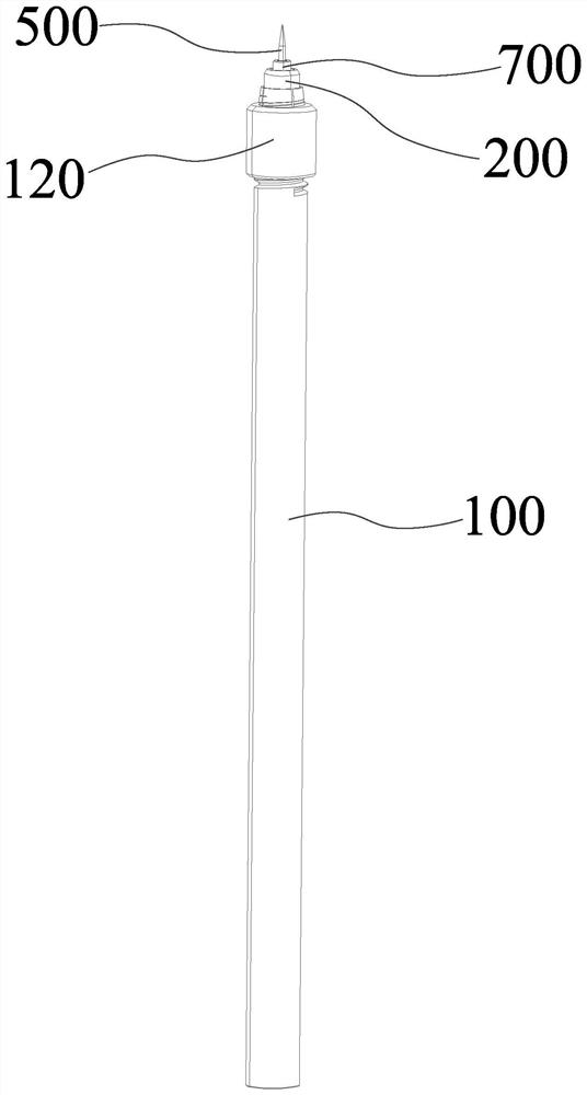
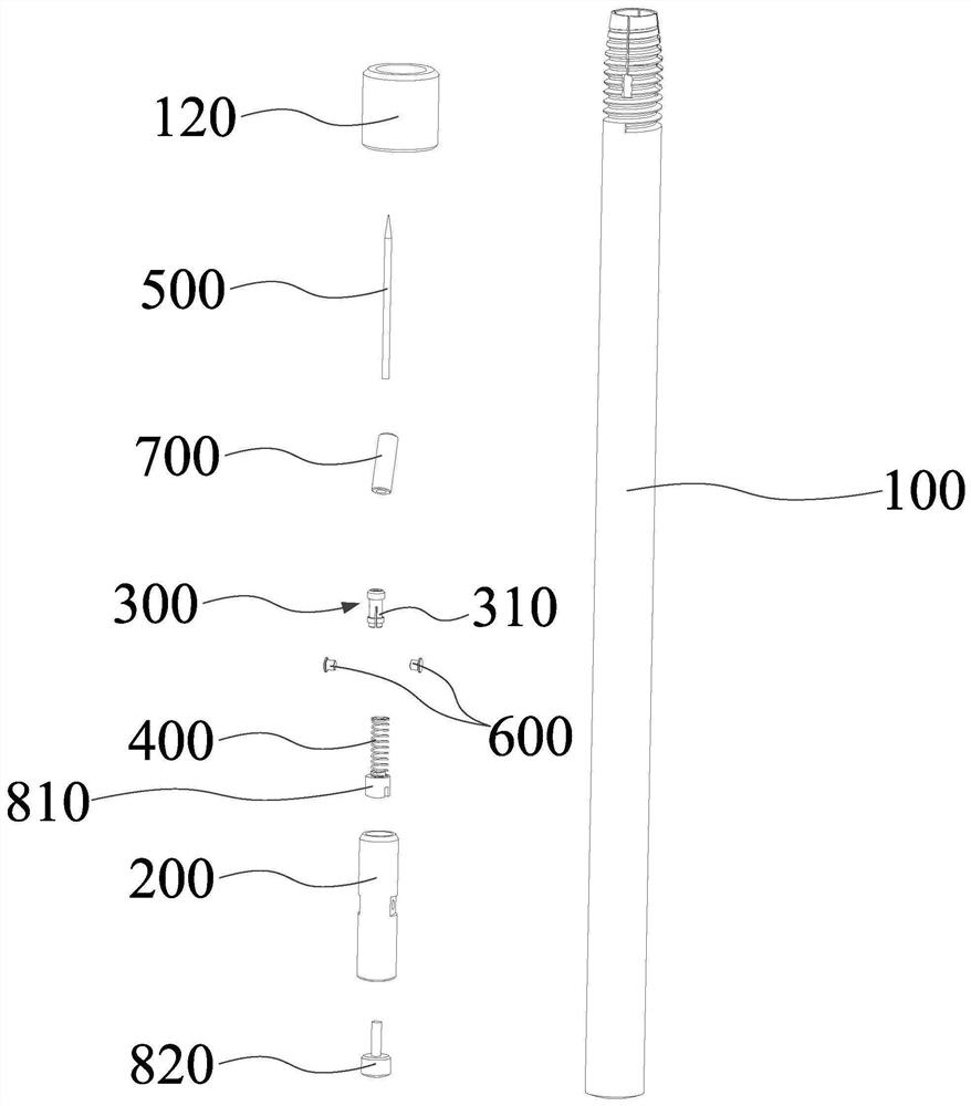
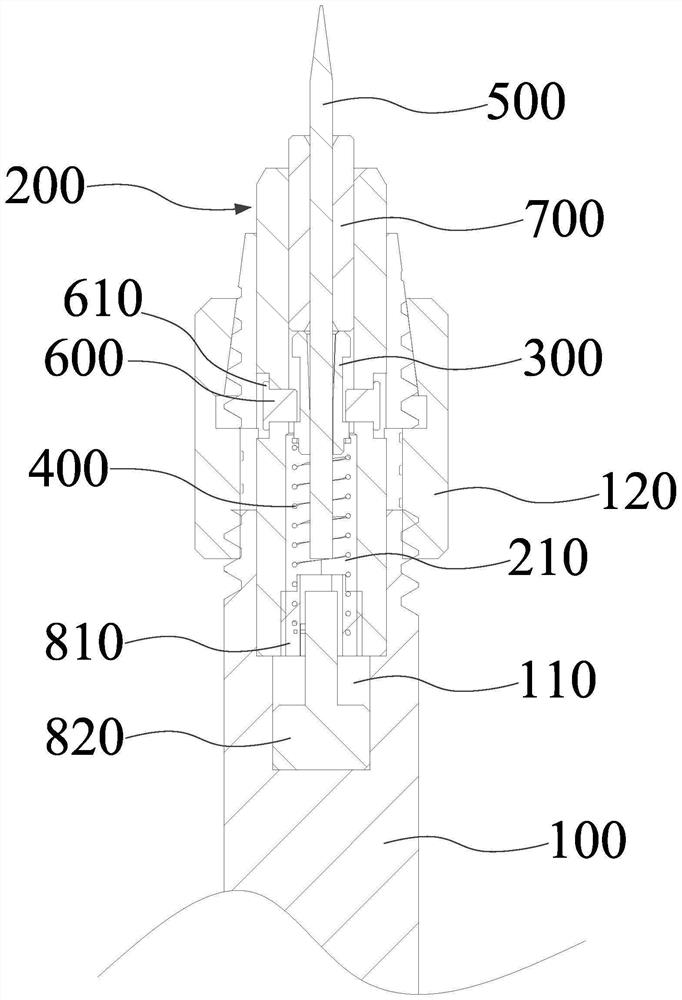
The invention provides an ejector pin mechanism and crystal ejection equipment. The ejector pin mechanism comprises a crystal ejection pin; a mounting hole is formed in the thimble sleeve along the axial direction of the thimble sleeve; the ejector pin sleeve is installed in the installation hole in a sliding mode, an inserting and penetrating part is arranged on the ejector pin sleeve, and the inserting and penetrating part is used for being unfolded to clamp the ejector pin when the ejector pin penetrates through the ejector pin sleeve and is used for being folded when the ejector pin is pulled out; one end of the elastic piece abuts against the ejector pin sleeve, and the other end abuts against the ejector pin sleeve. The crystal ejecting equipment comprises the ejector pin mechanism and the fine adjustment mechanism. According to the ejector pin mechanism, hard contact between the ejector pin and the chip can be reduced by arranging the elastic piece. When the ejector pin mechanism is replaced, the ejector pin can be directly replaced by an external tool or manual work, compared with the whole ejector pin mechanism, the ejector pin is easier to replace, and the replacement efficiency of the ejector pin is improved. And meanwhile, the ejector pin mechanism does not need to be integrally replaced, so that cost is saved.

Description

technical field [0001] This application belongs to the technical field of crystal bonding, and more specifically relates to a thimble mechanism and crystal topping equipment. Background technique [0002] In the existing LED (light-emitting diode, light-emitting diode) die-bonding process, a thimble mechanism is required to eject the chips carried on the blue film one by one. Crystal bit. [0003] In the prior art, the ejector mechanism includes an ejector pin and a rod body, and the ejector pin and the rod body are of an integrated structure. The rod body is fastened to the lifting unit, and the lifting unit drives the thimble mechanism to rise or fall. However, when the ejector pin needs to be replaced, the entire ejector pin mechanism needs to be removed from the lifting unit and replaced with a new ejector pin mechanism, which is inconvenient to operate and affects the replacement efficiency. Contents of the invention [0004] The purpose of the embodiments of the p...

Claims


Application Information

Patent Timeline
Patent Type & Authority Applications(China)
IPC IPC(8): H01L21/687H01L21/67
CPCH01L21/68742H01L21/67132Y02P70/50
Inventor 黄岗曾国鹏严楚雄胡新平
Owner SHENZHEN XINYICHANG TECH CO LTD
Learn More