
Miniaturized multichannel wavelength division demultiplexing optical receiving assembly

A technology of wave division multiplexing and multiplexing of light, which is applied in the field of optical communication devices, can solve the problems of large wavelength drift with temperature, high insertion loss, narrow bandwidth, etc., achieve small wavelength variation coefficient with temperature, reduce assembly difficulty and cost low effect

Pending Publication Date: 2022-03-01
FUZHOU PHOTOP QPTICS CO LTD
View PDF0 Cites 0 Cited by
  • Summary
  • Abstract
  • Description
  • Claims
  • Application Information

AI Technical Summary

Problems solved by technology

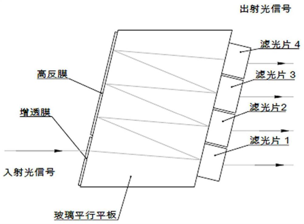
Although this assembly method is simple and efficient, there is still a big gap in the performance of AWG in the existing technology compared with Z-BLOCK, mainly reflected in the high insertion loss, narrow bandwidth, and large wavelength drift with temperature as mentioned above. , poor crosstalk and other key indicators, so AWG can only be used in some scenarios that do not require high performance and environment

Method used


Image

  • Miniaturized multichannel wavelength division demultiplexing optical receiving assembly
  • Miniaturized multichannel wavelength division demultiplexing optical receiving assembly
  • Miniaturized multichannel wavelength division demultiplexing optical receiving assembly

Examples


Embodiment 1

[0089] The 3D schematic diagram of Embodiment 1 of the present invention is as follows Figure 4 As shown, the two-dimensional structure schematic diagram is shown in Figure 5 or Figure 6 shown.

[0090] Miniaturized multi-channel wave division multiplexing optical receiving components, including:

[0091] Fiber collimator 1, for inputting collimated signal light;

[0092] The first wave division multiplexing subassembly 2 is used to decomplex the signal light input by the fiber collimator into several beams of signal light;

[0093] Right-angle prism 3, its rectangular surface is opposite to the output end of the wave division multiplexing subassembly and is used to receive some beams of collimated light decomplexed by the first wave division multiplexing subassembly 2, and then after being reflected by its slope, several A beam of collimated light is output from another rectangular surface of the rectangular prism 3;

[0094] The lens array 4 is arranged on the right-...

Embodiment 2

[0112] The structural representation of embodiment 2 of the present invention is as Figure 9 or Figure 10 shown. In this embodiment, the difference from Embodiment 1 is that the second wave division multiplexing subassembly 6 (1x2 beam splitter structure) of Embodiment 1 is replaced with a 1x2 Z-BLOCK structure; compared with the beam splitter structure, The Z-BLOCK structure greatly reduces the difficulty of WDM coating, which helps to improve yield and reduce cost.

[0113] Other details of this embodiment are implemented in the same manner as in Embodiment 1 (that is, components corresponding to the numbers are the same as those in Embodiment 1), and will not be repeated here.

Embodiment 3

[0115] The structural representation of Embodiment 3 of the present invention is as follows Figure 11 or Figure 12 Shown; In this embodiment, the only difference from Embodiment 1 is that the lens array is attached to the exit surface of the rectangular prism 3, and at this time, a lens array with a shorter focal length can be selected to obtain a smaller focal length on the focal plane. The size of the light spot, this structure can meet the application occasions where the PD receiving area is small. At this time, it can be ensured that the position of the focal plane of the focused spot coincides with the position of the PD receiving surface by strictly controlling the thickness of the optical substrate 5 .

[0116] In order to achieve a smaller phase difference, when selecting the lens array, you can use such as Figure 13 , Figure 14 Convex sinking lens array (Recession Lens Array) shown. At this time, the steps of the convex surface can be attached to the exit surf...


PUM

PropertyMeasurementUnit
diameteraaaaaaaaaa

Abstract

The invention discloses a miniaturized multi-channel wavelength division demultiplexing optical receiving assembly, which comprises an optical fiber collimator, a wavelength division demultiplexing module and a wavelength division multiplexing module, a first wavelength division demultiplexing subassembly; one right-angle surface of the right-angle prism is opposite to the output end of the wavelength division demultiplexing sub-assembly, and the right-angle prism is used for receiving the plurality of collimated light beams demultiplexed by the wavelength division demultiplexing sub-assembly and outputting the plurality of collimated light beams from the other right-angle surface of the right-angle prism after the plurality of collimated light beams are reflected by the inclined surface of the right-angle prism; the lens array is arranged on the right-angle surface, opposite to the wavelength division demultiplexing subassembly, of the right-angle prism; the optical substrate is used for relatively and fixedly mounting the optical fiber collimator, the wavelength division demultiplexing subassembly and the rectangular prism; and the second wavelength division demultiplexing sub-assembly is arranged behind the optical fiber collimator and is used for dividing an optical signal input by the optical fiber collimator into N strands and correspondingly inputting the N strands of optical signal into the first wavelength division demultiplexing sub-assembly, and the second wavelength division demultiplexing sub-assembly is also fixedly connected with the optical substrate. The scheme is excellent in performance, and completely meets industrial standards related to optical communication.

Description

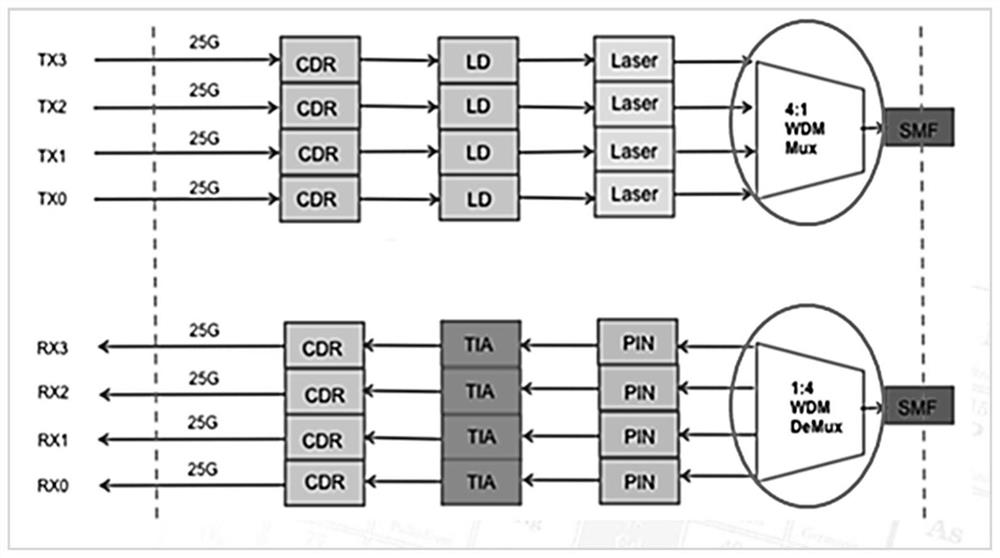
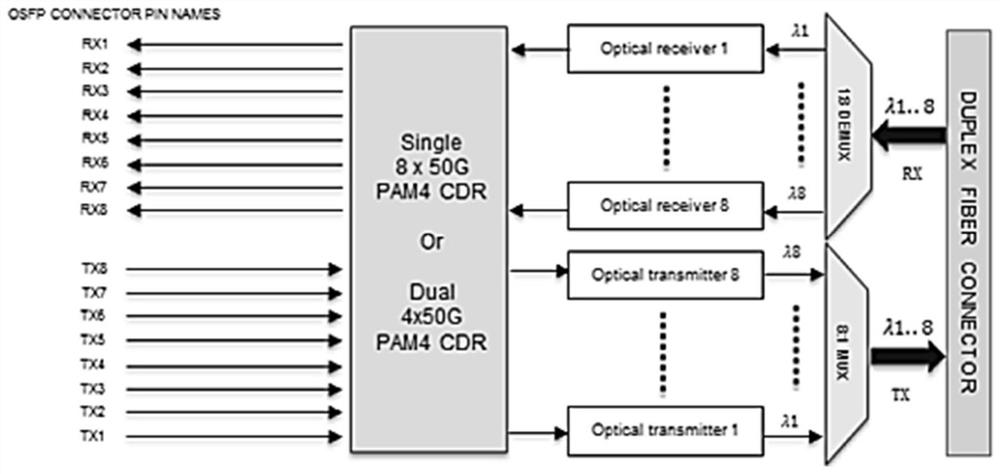
technical field [0001] The invention relates to the technical field of optical communication devices, in particular to a miniaturized multi-channel wave division multiplexing optical receiving component. Background technique [0002] Wavelength Division Multiplexing (WDM, Wavelength Division Multiplexing) is to combine two or more optical carrier signals of different wavelengths (carrying various information) at the sending end through a multiplexer (also known as a multiplexer, Multiplexer, MUX for short) Together, and coupled to the same optical fiber of the optical line for transmission; at the receiving end, the optical carriers of various wavelengths are separated by a demultiplexer (also known as a demultiplexer, Demultiplexer, DEMUX for short), and then transmitted by The optical receiver does further processing to recover the original signal. This technology of simultaneously transmitting two or more optical signals of different wavelengths in the same optical fiber...

Claims


Application Information

Patent Timeline
Patent Type & Authority Applications(China)
IPC IPC(8): G02B6/293G02B6/34G02B6/32
CPCG02B6/2938G02B6/29373G02B6/34G02B6/32
Inventor 贾旭于光龙林应龙
Owner FUZHOU PHOTOP QPTICS CO LTD
Learn More