Oil pipe stamping equipment capable of preventing bulges on two sides
A technology for stamping equipment and oil pipes, which is applied in the field of anti-bulge oil pipe stamping equipment on both sides, which can solve problems such as warping (bulges, damage at both ends of oil pipes, and failure to combine) on both sides, so as to avoid deviation and improve construction efficiency. Force strength, the effect of ensuring stability
- Summary
- Abstract
- Description
- Claims
- Application Information
AI Technical Summary
Problems solved by technology
Method used
Image
Examples
Embodiment 1
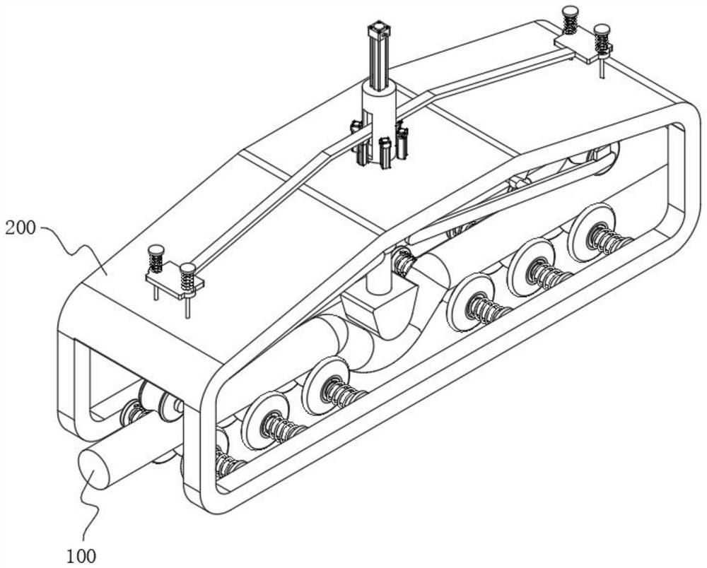
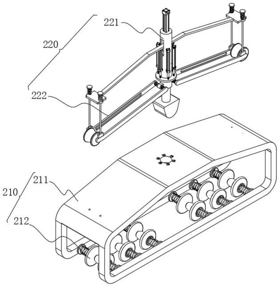
[0050] see figure 1 and figure 2 As shown, the purpose of this embodiment is to provide a two-sided anti-bulge oil pipe stamping equipment, including a fuel pipe piece 100 and a stamping device 200 arranged outside the oil pipe piece 100 for stamping it. The stamping device 200 includes an external mechanism 210 and Stamping mechanism 220, external mechanism 210 comprises outer frame 211 and force-bearing support 212, and force-bearing support 212 is arranged on the bottom of outer frame 211, forms insertion cavity between outer frame 211 and force-bearing support 212, during use, oil The pipe 100 is inserted into the cavity and then stamped by a stamping mechanism 220, wherein:
[0051] see image 3 As shown, the stamping mechanism 220 includes a stamping part 221 and a side-end holding part 222. The stamping part 221 includes a primary stamping column 2211, a secondary stamping column 2212, and a stamping head 2213. The primary stamping column 2211 and the secondary stamp...
Embodiment 2
[0057] In order to ensure the force strength of the side pressure frame 2221, please refer to Figure 5 As shown, a pressure member 223 is set between the side pressure frame 2221 and the inner wall of the outer frame 211, please refer to Figure 6 As shown, the pressing part 223 includes a sliding sleeve 2231, the top of the sliding sleeve 2231 is rotatably connected with an adapter seat 2235, and the adapter seat 2235 is fixedly connected with the inner wall of the outer frame 211. The pressing part 223 also includes a sliding column 2232, and the sliding column 2232 It is arranged at the bottom of the sliding sleeve 2231 and is slidably connected with it. A pressurizing spring 2234 is also fixedly connected between the sliding sleeve 2231 and the sliding column 2232. During specific work, the bottom end of the sliding column 2232 is symmetrically provided with a sliding rod 2233, and the side pressure The frame 2221 is a hollow structure, and there are chute 2225 on the inn...
Embodiment 3
[0059] Considering that oil pipes 100 have different thicknesses, but the cross-sections are all circular, the limit strength of the plate structure and rollers is not enough, and it cannot be adjusted according to different thicknesses. For this, please refer to Figure 7 and Figure 8 As shown, the force supporting member 212 includes a support column 2121, the support column 2121 is fixedly connected with the outer frame 211, a shaping wheel 2123 is arranged on the middle position of the support column 2121, and the two sides of the shaping wheel 2123 are symmetrically provided with a force wheel 2122 , between the stressed wheel 2122 and the shaping wheel 2123 and the supporting column 2121 are rotationally connected, the stressed spring 2124 is arranged between the stressed wheel 2122 and the flange at the end of the supporting column 2121, and the stressed spring 2124 is connected to the supporting column 2121 The flange at the end is fixedly connected, and the stressed ...
PUM
 Abstract
Description
Claims
Application Information
 - Generate Ideas
- Intellectual Property
- Life Sciences
- Materials
- Tech Scout
- Unparalleled Data Quality
- Higher Quality Content
- 60% Fewer Hallucinations
Browse by: Latest US Patents, China's latest patents, Technical Efficacy Thesaurus, Application Domain, Technology Topic, Popular Technical Reports.
© 2025 PatSnap. All rights reserved.Legal|Privacy policy|Modern Slavery Act Transparency Statement|Sitemap|About US| Contact US: help@patsnap.com


