
Control method of automatic lifting device for auxiliary disassembly and assembly of mutual inductor in box transformer substation

An automatic lifting and device control technology, applied in the direction of lifting devices, user/computer interaction input/output, neural learning methods, etc., can solve problems that cannot fully meet the lifting environment, cannot realize automatic and precise control of lifting devices, and achieve recognition The effect of high degree, strong applicability and easy system

Pending Publication Date: 2022-02-25
HANGZHOU ELECTRIC EQUIP MFG +2
View PDF0 Cites 0 Cited by
  • Summary
  • Abstract
  • Description
  • Claims
  • Application Information

AI Technical Summary

Problems solved by technology

However, due to the different working environments, the lifting devices on the market cannot fully meet all lifting environments.
At present, the participation of the lifting device is required in the disassembly and maintenance process of the internal parts of the box-type substation, but the lifting device used at present requires manual control of the lifting device and the left and right movement of the lifting device, which cannot realize automatic and precise control of the lifting device. Only 2-3 people can complete the disassembly and assembly of large parts in the box-type substation

Method used


Image

  • Control method of automatic lifting device for auxiliary disassembly and assembly of mutual inductor in box transformer substation
  • Control method of automatic lifting device for auxiliary disassembly and assembly of mutual inductor in box transformer substation
  • Control method of automatic lifting device for auxiliary disassembly and assembly of mutual inductor in box transformer substation

Examples


Embodiment Construction

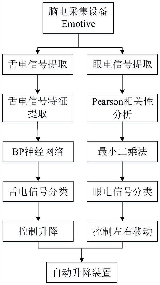
[0029] The present invention will be further described below in conjunction with the accompanying drawings and embodiments.

[0030] refer to figure 1 , a specific embodiment of an automatic lifting device control method for auxiliary disassembly and assembly of transformers in a box-type transformer, including tongue electrical signal control and eye electrical signal control. Tongue electric signal control specifically includes the following steps:

[0031] Step 1. Use the EEG acquisition device Emotive to collect EEG signals;

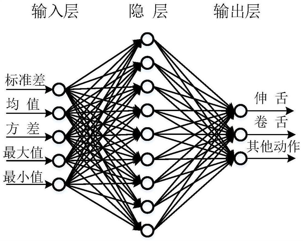
[0032] Step 2. Select the EEG signals of leads AF3 and AF4 as the identification object of the tongue electric signal;

[0033] Step 3. Use the moving rectangular window with a step size of 100 sampling points to move on the selected lead EEG signal, and calculate the five characteristics of the EEG signal's maximum value, minimum value, mean value, standard deviation and variance in the moving rectangular window .

[0034] Step 4.1, according to...


PUM


Abstract

The invention discloses a control method of an automatic lifting device for auxiliary disassembly and assembly of a mutual inductor in a box transformer substation, the control method comprises tongue electric signal control and eye electric signal control, and the tongue electric signal control uses a BP neural network to identify tongue electric signals of a human tongue in different states so as to control the lifting of the lifting device; the eye electric signal control comprises the following steps: firstly, recognizing an eye movement signal through Pearson correlation analysis, and secondly, fitting a local slope of the signal so as to identify a left eye movement signal and a right eye movement signal to control the left and right movement of the automatic lifting device. The lifting and left-right movement of the automatic lifting device are controlled by recognizing human body physiological signals, in the narrow space of the box transformer, one person can disassemble and assemble large components such as a mutual inductor in the box transformer, assistance of other operators is not needed, labor force is saved, the recognition degree is high, the system is easy to establish, the method is easy to implement. The automatic lifting device has the advantages of being scientific, reasonable, high in applicability and the like.

Description

technical field [0001] The invention relates to a control method for real-time control of an automatic lifting device, in particular to a control method for an automatic lifting device used for auxiliary disassembly and assembly of a transformer in a box-type transformer. Background technique [0002] The lifting device is mainly used for material transmission, parts positioning, etc., which can not only improve the automation of the equipment, but also improve the processing flexibility of the equipment. The lifting devices that exist on the market mainly include worm gear screw lifts, lifting platforms, screw nut lifting mechanisms, rack and pinion lifting mechanisms, bevel gear lifting mechanisms, belt lifting, chain lifting, etc. However, due to the different working environments, the lifting devices on the market cannot fully meet all lifting environments. At present, the participation of the lifting device is required in the disassembly and maintenance process of the ...

Claims


Application Information

Patent Timeline
IPC IPC(8): G06F3/01G06N3/08G06V40/19G06V40/20G06N3/02B66F13/00
CPCG06F3/015G06N3/084G06N3/02B66F13/00
Inventor 王辉东刘凤赵奇剑叶凌霄崔金栋沈建浩施苗根应雪明王妮佳
Owner HANGZHOU ELECTRIC EQUIP MFG
Learn More