Laser radar emission angle detection system

A laser radar and detection system technology, applied in radio wave measurement systems, measurement devices, optical devices, etc., can solve problems such as high space requirements, inconvenient detection, and difficulty in mass production, achieving small size, convenient maintenance, and compatibility. strong effect

Pending Publication Date: 2022-02-25
ZHONGSHAN UVATA OPTICAL
View PDF0 Cites 0 Cited by
  • Summary
  • Abstract
  • Description
  • Claims
  • Application Information

AI Technical Summary

Problems solved by technology

Due to the long distance, the laser radar light spot is easy to fall outside the imaging surface of the chip, and the CCD needs to be moved to receive the image, which has disadvantages such as inconvenient detection, high space requirements, and difficulty in mass production.

Method used


Image

  • Laser radar emission angle detection system
  • Laser radar emission angle detection system

Examples


Embodiment Construction

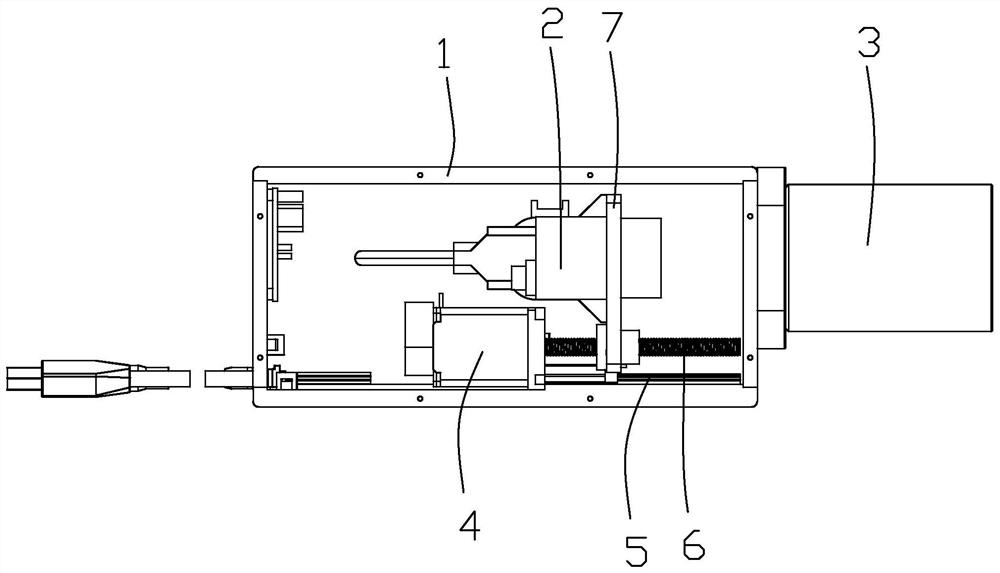
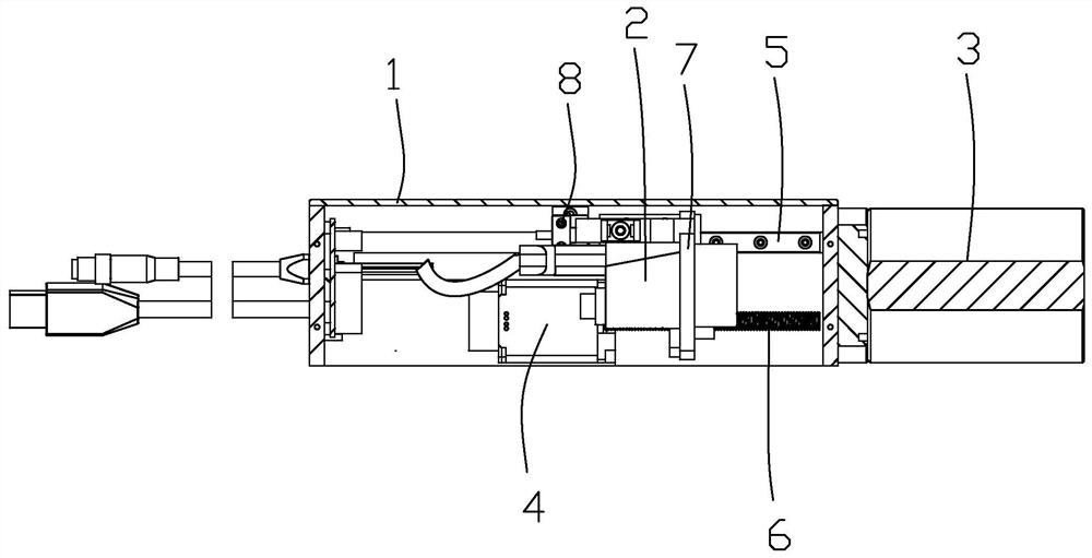
[0018] Advantages and features of the present disclosure, and implementation methods thereof will be clarified through the following embodiments described with reference to the accompanying drawings. However, this disclosure may be embodied in different forms and should not be construed as limited to the embodiments set forth herein. Rather, these embodiments are provided so that this disclosure will be thorough and complete, and will fully convey the scope of the disclosure to those skilled in the art. Furthermore, the present disclosure is limited only by the scope of the claims.

[0019] The shapes, dimensions, proportions, angles and numbers disclosed in the drawings for describing the embodiments of the present disclosure are examples only, and thus the present disclosure is not limited to the shown details. Throughout this specification, the same reference numerals refer to the same elements. In the following description, when a detailed description of a related known ...


PUM


Abstract

The invention discloses a laser radar emission angle detection system. The system is characterized by comprising a box body, a CCD camera, a teleconverter and a moving mechanism for driving the CCD camera to move are arranged in the box body, and a light beam emitted by a laser radar module is received by the CCD camera after passing through the teleconverter. The laser radar angle measurement system is small in size, the detection distance can be adjusted by a software, the simulation distance precision is high, and the problems that the traditional laser radar emission angle detection requires large space and is inconvenient, can be solved.

Description

technical field [0001] The invention relates to an optical detection system, in particular to a laser radar emission angle detection system. Background technique [0002] Since the detection distance of the lidar module is long, often greater than 50 meters, there will be a difference between the short-distance detection and the actual long-distance use. [0003] The existing laser radar emission angle detection process basically projects the laser radar onto a diffuse reflection target 50 meters away, and calculates the laser radar emission angle by shooting the radar spot on the target with a CCD camera. Due to the long distance, the laser radar light spot is easy to fall outside the imaging surface of the chip, and the CCD needs to be moved to receive the image, which has disadvantages such as inconvenient detection, high space requirements, and difficulty in mass production. Contents of the invention [0004] In order to overcome the deficiencies of the prior art, the...

Claims


Application Information

Patent Timeline
Patent Type & Authority Applications(China)
IPC IPC(8): G01B11/26G01S7/497
CPCG01B11/26G01S7/497
Inventor 谭冬衡舒光兵王瑶曹玉坚
Owner ZHONGSHAN UVATA OPTICAL
Why Eureka
Try Eureka