Bolt machining process and feeding mechanism thereof
A technology of feeding mechanism and discharging mechanism, which is applied in metal processing and other directions, can solve problems such as uneven bolt processing quality, inaccurate judgment, and inconvenient loading and unloading, so as to improve bolt processing quality, work efficiency, and safe and stable discharging Effect
- Summary
- Abstract
- Description
- Claims
- Application Information
AI Technical Summary
Problems solved by technology
Method used
Image

Examples
Embodiment 1
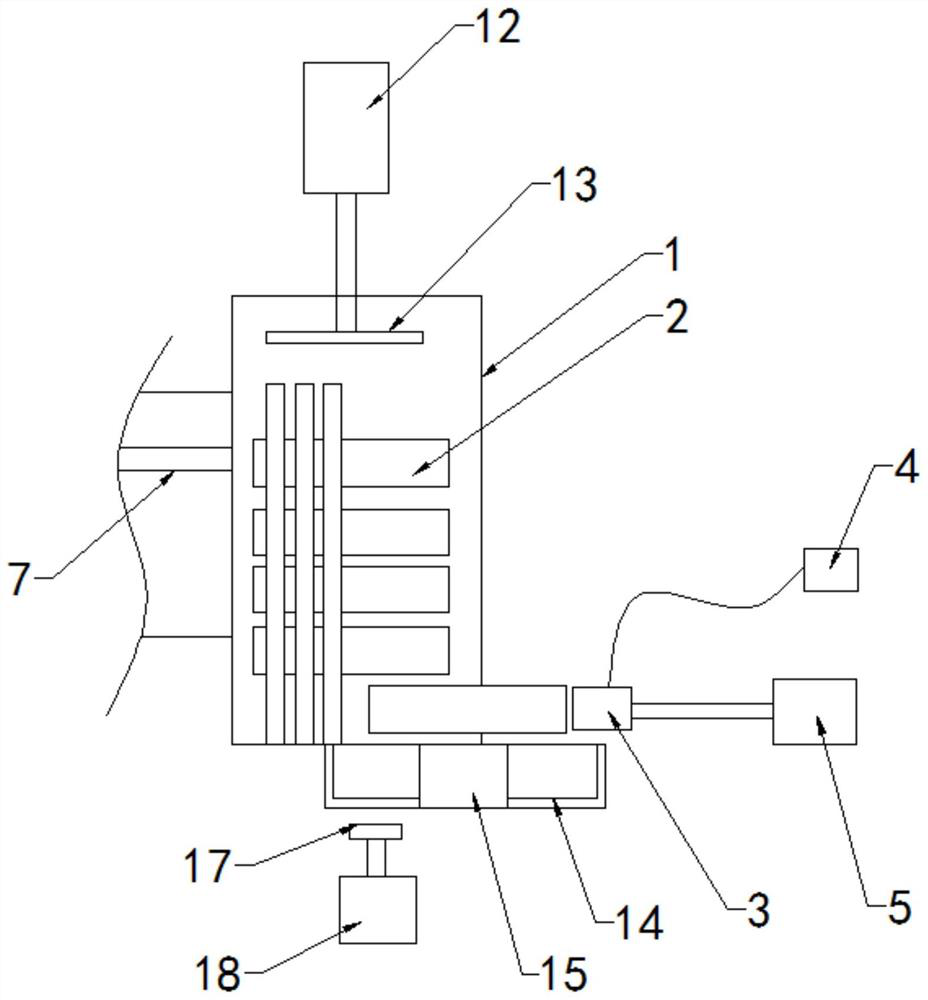
[0030] The invention discloses a feeding mechanism. In a specific embodiment of the invention, it includes a discharging mechanism, which is arranged on one side of the heating furnace 1, and is used to take out the steel section 2 that has been heated in the heating furnace 1; the discharging The mechanism includes an adsorption part, which can fix the steel section in the heating furnace 1 by adsorption; a control part, which is connected with the adsorption part to control the on-off of the adsorption force of the adsorption part; and a moving mechanism, which is connected with the adsorption part to control the entry and exit of the adsorption part from the heating furnace 1; In this embodiment, the adsorbing part is an electromagnetic coil 3, the control part is an electromagnetic control device 4 for controlling the energization of the electromagnetic coil 3 so as to control the presence or absence of the adsorption force of the electromagnetic coil 3, and the moving mecha...
Embodiment 2
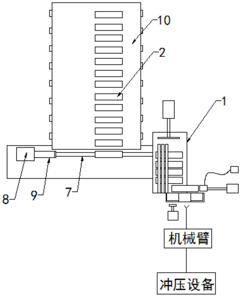
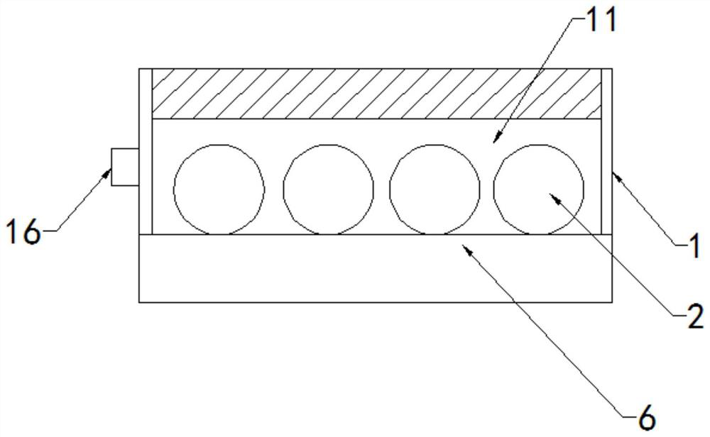
[0034] Such as Figure 1~3As shown, the difference between this embodiment and Embodiment 1 is that in this embodiment, the feeding of the steel section passes through the feeding mechanism, and the feeding mechanism includes a feeding unit for pushing the steel section into the In the heating furnace 1; the conveying unit is used to sequentially transport the steel sections to the feeding unit; wherein, the feeding unit includes a slideway 7 that is as high as the loading platform 6 of the heating furnace 1, and is installed on the slideway 7 away from the heating furnace 1. The second cylinder 8 on the side and the push rod 9, the steel section is supported by the slideway 7 and is slidably connected with the slideway 7, and the push rod 9 is set on the output end of the second cylinder 8 and is controlled by the second cylinder 8 to move left and right; The conveying unit includes a conveying belt 10, and the steel sections on the conveying belt 10 are sequentially conveyed...
Embodiment 3
[0040] Such as Figure 4 ~ Figure 6 As shown, the difference between this embodiment and Embodiment 2 is that: in this embodiment, a limit mechanism is also provided in the carrying platform, and the limit mechanism includes a limit bar 19, which is evenly arranged on the carrying platform , and set in parallel with the steel sections, each steel section is located between two limit strips 19; the limit cavity 20 is set inside the carrying platform; the adsorption magnetic strip 21 is located in the limit cavity 20, which can hold the load The upper steel segment creates suction.
[0041] In this embodiment, the limiting mechanism also includes a threaded column 22, which is installed vertically in the limiting cavity 20, and the upper and lower ends are rotatably connected to the inner wall of the limiting cavity 20 through bearings; On the threaded column 22, the threaded sleeve 23 is fixedly connected with the magnetic strip 21; the adjusting screw 24 is inserted into the ...
PUM
 Abstract
Description
Claims
Application Information
 - R&D
- Intellectual Property
- Life Sciences
- Materials
- Tech Scout
- Unparalleled Data Quality
- Higher Quality Content
- 60% Fewer Hallucinations
Browse by: Latest US Patents, China's latest patents, Technical Efficacy Thesaurus, Application Domain, Technology Topic, Popular Technical Reports.
© 2025 PatSnap. All rights reserved.Legal|Privacy policy|Modern Slavery Act Transparency Statement|Sitemap|About US| Contact US: help@patsnap.com