
Assembly type base plate for powder bed melting additive manufacturing and using method thereof

An additive manufacturing and assembly technology, applied in the field of fabricated substrates for powder bed melting additive manufacturing, can solve the problems of small additive manufacturing samples, difficult processing of special-shaped grooves and special-shaped sliders, etc. The effect of reducing manufacturing costs and reducing assembly errors

Pending Publication Date: 2022-02-25
BEIJING UNIV OF TECH
View PDF3 Cites 4 Cited by
  • Summary
  • Abstract
  • Description
  • Claims
  • Application Information

AI Technical Summary

Problems solved by technology

In the process of exploring the process, manufacturing with traditional substrates often brings a lot of inconvenience
Traditional substrates are often used to manufacture bulk parts with a characteristic size of more than 5cm, while some additive manufacturing samples used for testing purposes are small, with a characteristic size of less than 1cm
However, the processing of special-shaped grooves and special-shaped sliders is usually difficult, and positioning by distinguishing a large number of grid lines can easily lead to wrong number of grid lines

Method used


Image

  • Assembly type base plate for powder bed melting additive manufacturing and using method thereof
  • Assembly type base plate for powder bed melting additive manufacturing and using method thereof
  • Assembly type base plate for powder bed melting additive manufacturing and using method thereof

Examples


Embodiment 1

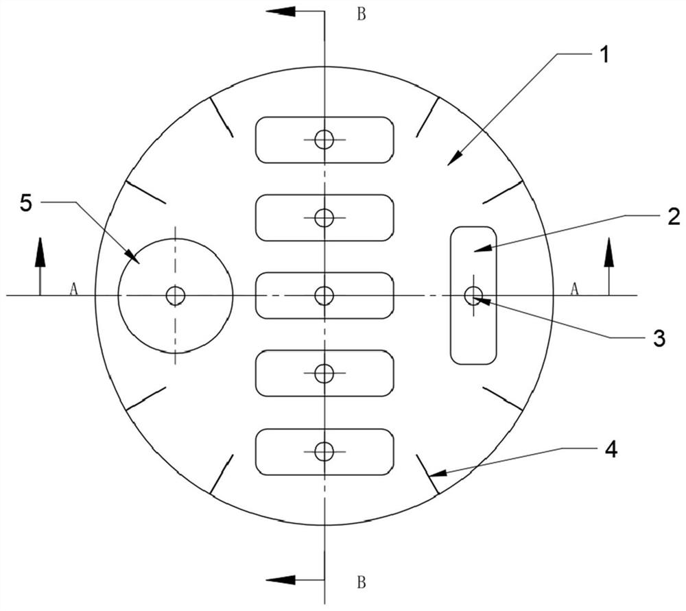
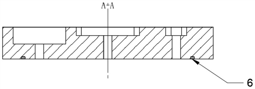
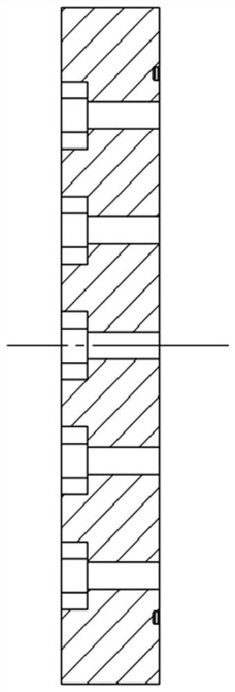
[0041] This embodiment provides an assembled substrate for powder bed melting additive manufacturing and a method for using the same. Such as figure 1 As shown, the assembled substrate includes a standard substrate 1 , a rounded rectangular groove 2 , a through hole 3 - 1 in the assembly groove, a scoring line 4 and a circular groove 5 . The standard substrate 1 is provided with six rounded rectangular slots 2 for accommodating small rounded rectangular substrates, and a circular slot 5 for accommodating a small circular substrate 7, and a through hole 3- 1. Wherein, the cross-section A-A of the standard substrate 1, such as figure 2 shown. Cross-section B-B of standard substrate 1, such as image 3 shown. The bottom of the standard substrate 1 is provided with a sealing ring groove 6 . The rounded rectangular small substrate 7 in this embodiment, such as Image 6 shown.

[0042] The basic style of the standard substrate 1 refers to the standard substrate drawing of t...

Embodiment 2

[0046] The assembled substrate for powder bed melting additive manufacturing provided in this embodiment, such as Figure 4-5 As shown, the same as embodiment 1, the difference is that the through holes are changed into bolt holes. The basic style of the standard substrate 1 refers to the standard substrate drawing of the EOS M100 model printer, with a diameter of 100mm and a sealing ring groove 6 for positioning and fixing at the bottom. The depth of the rounded rectangular groove 2 is 4mm, and its shape is a rectangular chamfer of 30mm×10mm with 2.5mm. The depth of the circular groove is 8 mm and its shape is a circle with a diameter of 25 mm. The center position of each groove opens the bolt hole of M6 or M8.

[0047] The method for reusing the assembled substrate for powder bed melting additive manufacturing provided in this embodiment includes: first placing the standard substrate 1 on a flat and firm working platform. Align the small substrate 7 with the notch and pla...

Embodiment 3

[0050] Using the fabricated substrate for powder bed melting additive manufacturing and the method of use in Embodiment 2, the difference is: firstly, the standard substrate 1 is placed on a flat and firm working platform. The small substrate 7 is cooled and shrunk in liquid nitrogen, then taken out with clamps, quickly put into the assembly groove 2, and the interference fit can be realized after the small substrate 7 is heated to room temperature. Take a deflection meter to detect whether the assembly accuracy of the small substrate 7 and the standard substrate 1 meets the requirements. After all the assembly slots 2 of the standard substrate 1 are filled, the standard substrate 1 is positioned on the printing platform of the printer according to the sealing ring groove 6 . Finally, the printing position of the substrate is adjusted according to the positioning line 4 on the standard substrate to ensure that the actual printing position coincides with the printing area set b...


PUM

PropertyMeasurementUnit
diameteraaaaaaaaaa

Abstract

The invention relates to the field of metal powder bed melting additive manufacturing, in particular to an assembly type base plate for powder bed melting additive manufacturing and a using method thereof. The assembly type base plate comprises a standard substrate, at least one assembly groove is formed in the standard substrate, and a through hole is formed in the bottom of the assembly groove; and the base plate also includes small substrates that are in one-to-one correspondence with the assembly grooves, the small substrates are embedded in the assembly grooves in the standard substrate, and the small substrates are detachably mounted on the standard substrate. According to the invention, the product and the small substrate can be conveniently taken down from the main substrate; the standard substrate does not need to be leveled after one-time printing is completed, so that the production preparation time is greatly shortened, the production efficiency is improved, and the processing cost is reduced; and after the products are formed and manufactured, the small forming substrates can be detached from the standard substrate, so that the products can be independently treated according to detection requirements, and the utilization rate of equipment is improved.

Description

technical field [0001] The invention relates to the field of metal powder bed melting additive manufacturing, in particular to an assembled substrate for powder bed melting additive manufacturing and a method for using the same. Background technique [0002] Metal powder bed melting has good development potential and market application prospects in metal additive manufacturing. According to the different energy beams used in processing, metal powder bed melting technology can be mainly divided into laser powder bed melting technology and electron beam melting technology. The processing process is generally to spread powder layer by layer on the prefabricated substrate, select the area that needs to be scanned by high-energy beam current on the current layer according to the model slice, and cycle back and forth to obtain the molded parts, and then cut and separate the parts from the substrate. [0003] At present, the development of metal powder bed melting technology is no...

Claims


Application Information

Patent Timeline
Patent Type & Authority Applications(China)
IPC IPC(8): B22F12/30B22F10/28B33Y10/00B33Y30/00
CPCB22F12/30B22F10/28B33Y10/00B33Y30/00Y02P10/25
Inventor 贺定勇吴海荣郭星晔周正谈震吴旭邵蔚王国红
Owner BEIJING UNIV OF TECH
Learn More