Pipe well post-pouring hole advanced construction pipeline reservation construction system

A technology of tube wells and pipelines, which is applied in the field of tube well post-casting and advance construction pipeline reservation construction system, which can solve the problems of inconvenient concrete transportation, poor construction quality, and difficulty in formwork support, so as to reduce the amount of high-strength concrete and save construction Cost, effect of ensuring construction safety

Pending Publication Date: 2022-02-18
CHINA CONSTR EIGHT ENG DIV CORP LTD
View PDF0 Cites 0 Cited by
  • Summary
  • Abstract
  • Description
  • Claims
  • Application Information

AI Technical Summary

Problems solved by technology

[0003] The technical problem to be solved by the present invention is to overcome the existing defects and provide a construction system for pipe well post-casting ahead of construction pipeline reservation to solve the traditional method of mechanical and electrical pipe well shaft structure plate proposed in the above background technology. During this period, the construction of the main structure is often completed, the concrete pouring pipeline is removed, and the concrete in the post-casting hole is usually transported by the construction elevator; the traditional method mainly has problems such as inconvenient concrete transportation, difficult formwork support, poor construction quality, and large safety hazards. question

Method used


Image

  • Pipe well post-pouring hole advanced construction pipeline reservation construction system
  • Pipe well post-pouring hole advanced construction pipeline reservation construction system
  • Pipe well post-pouring hole advanced construction pipeline reservation construction system

Examples


Embodiment 1

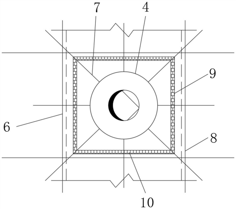
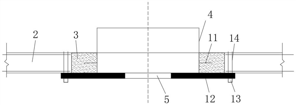
[0038] A tube well post-casting hole advance construction pipeline reservation structure, comprising a tube well formwork 1, a first formwork 2, a second formwork 3 and a post-pouring area 6, the tube well formwork 1 is composed of the first formwork 2, the second formwork 3 and the post-pouring area 6. The post-casting area 6 is composed of a casing 4 and a measuring wire hole 5. The casing 4 is provided with a measuring wire hole 5, and the outer side of the casing 4 is provided with a casing steel bar 7. The outside of the casing steel bar 7 is provided with a plate Reinforcement 8, casing steel reinforcement 7 and plate reinforcement 8 are provided with concrete secondary pouring boundary line 9, inside of concrete secondary pouring boundary line 9 is provided polystyrene board 10, inside second formwork 3 is provided with water stop ring 11 One side of the measurement release hole 5 is provided with a pipeline template 12, one side of the pipeline template 12 is provided w...

Embodiment 2

[0041] A method for reserving pipelines for post-casting tunnels in advance of construction of tube wells, comprising the following steps;

[0042] Step 1. The tube well formwork 1 is erected on the same floor as the structure main body. The first formwork 2 is set up in the same way as the structural slab of this layer. The second formwork 3 is fixed with the ribs 8 in the surrounding pre-cast structural slab through steel wires 14. When the post-casting area 6. When the area is large, wooden square 13 support can be set under the second formwork 3, steel wire 14 bypasses wooden square 13 and pours the surrounding structural plates simultaneously, casing 4 and casing reinforcement 7 are installed synchronously with plate reinforcement 8;

[0043]Step 2: Concrete the tube well structural slabs except the post-pouring area 6, and remove the formwork in the pre-pouring area when the formwork removal strength is reached;

[0044] Step 3. Accurately locate the pipeline by measurin...


PUM


Abstract

The invention discloses a pipe well post-pouring hole advance construction pipeline reservation construction system. The system comprises a pipe well formwork, a first formwork, a second formwork and a post-pouring area, wherein the pipe well formwork is composed of the first formwork, the second formwork and the post-pouring area, the post-pouring area is composed of a sleeve and a measuring pay-off hole, the measuring pay-off hole is formed in the sleeve, sleeve steel bars are arranged on the outer sides of the sleeves, plate ribs are arranged on the outer sides of the sleeve steel bars, concrete secondary pouring boundaries are arranged between the sleeve steel bars and the plate ribs, polystyrene plates are arranged on the inner sides of the concrete secondary pouring boundaries, and water stop wing rings are arranged in the second formwork; a pipeline formwork is arranged on one side of the measuring and setting-out hole, the formwork in the area can be reserved for a long time, and the formwork can be removed till the pipeline is accurately positioned, a sleeve is adjusted in place, concrete is poured on the periphery of the pipeline, and the formwork is dismounted after the formwork removal strength is achieved; and the template is immediately inserted into the pipeline for installation after being removed.

Description

technical field [0001] The invention belongs to the technical field of electromechanical pipeline installation, and in particular relates to a reserved construction system for pipelines for post-casting and advanced construction of tube wells. Background technique [0002] The traditional method for the structural slab of the electromechanical pipe well shaft is to pour the electromechanical pipes after installation. During this period, the main structure is often completed, the concrete pouring pipes are removed, and the post-casting concrete is usually transported by the construction elevator; the traditional method mainly has the inconvenience of concrete transportation and formwork support. Difficulties, poor construction quality, large safety hazards and other problems. Contents of the invention [0003] The technical problem to be solved by the present invention is to overcome the existing defects, and provide a construction system for pipe well post-casting ahead of...

Claims


Application Information

Patent Timeline
Patent Type & Authority Applications(China)
IPC IPC(8): E04G13/00E04G9/08E04G21/02E04G19/00E04G21/12E04G17/00H02G1/00H02G1/08
CPCE04G13/00E04G9/08E04G21/02E04G19/00E04G21/122E04G1/00H02G1/00H02G1/08
Inventor 丛利张元会吉柳彧赵文杰丁鲁波高健
Owner CHINA CONSTR EIGHT ENG DIV CORP LTD
Why Eureka
Try Eureka