
External circulation cleaning treatment method and system for cyanogen-containing SRG gas

An external circulation and gas technology, applied in gas treatment, separation methods, chemical instruments and methods, etc., can solve the problems of crystallization of sodium sulfite, increase of wastewater discharge, increase of alkali consumption, etc. The effect of blocking equipment and increasing acid production

Pending Publication Date: 2022-02-18
HUNAN ZHONGYE CHANGTIAN ENERGY CONSERVATION & ENVIRONMENTAL PROTECTION TECH CO LTD +1
View PDF7 Cites 0 Cited by
  • Summary
  • Abstract
  • Description
  • Claims
  • Application Information

AI Technical Summary

Problems solved by technology

On the one hand, the alkali consumption will increase sharply, resulting in the waste of liquid alkali and increasing the discharge of wastewater; in addition, during the process of adding alkali, sodium sulfite crystals will be formed and precipitated, causing system blockage and paralysis

Method used


Image

  • External circulation cleaning treatment method and system for cyanogen-containing SRG gas
  • External circulation cleaning treatment method and system for cyanogen-containing SRG gas
  • External circulation cleaning treatment method and system for cyanogen-containing SRG gas

Examples


Embodiment 1

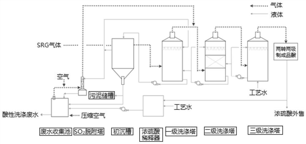
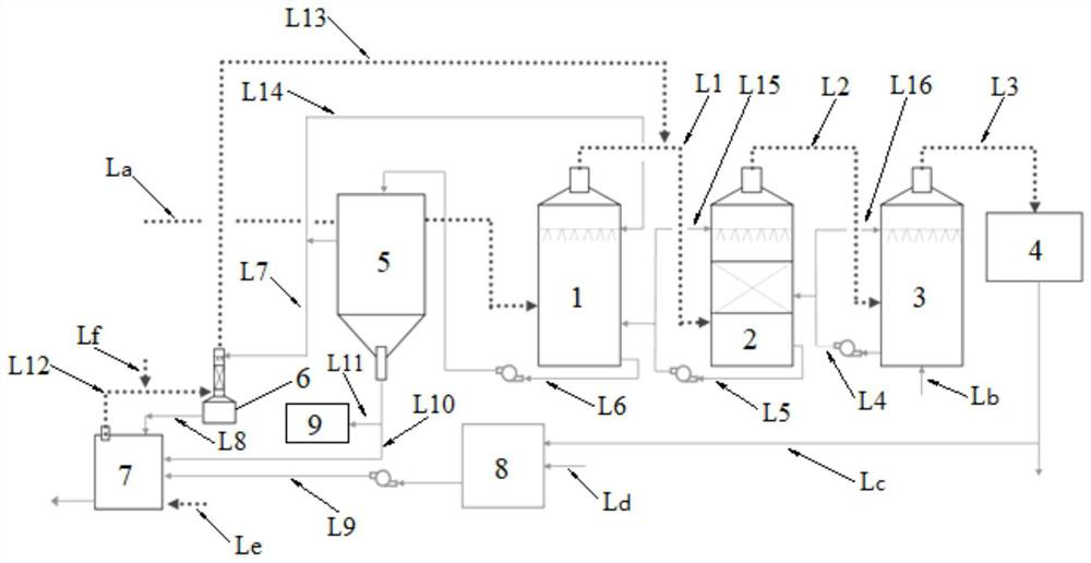
[0139] Such as figure 2 As shown, an external circulation cleaning treatment system for cyanide-containing SRG gas, the system includes: a primary scrubber 1, a secondary scrubber 2, a tertiary scrubber 3, an acid system 4, a primary sedimentation tank 5, SO 2 Desorption tower 6, waste water collection tank 7, concentrated sulfuric acid diluter 8. SRG Gas Delivery Pipeline L a Connected to the gas inlet of the primary scrubber 1, the gas outlet of the primary scrubber 1 is connected to the gas inlet of the secondary scrubber 2 via the first pipeline L1, and the gas outlet of the secondary scrubber 2 is connected to the gas outlet of the secondary scrubber 2 via the second pipeline L2 The gas inlet of the three-stage scrubber 3 and the gas outlet of the three-stage scrubber 3 are connected to the acid system 4 via the third pipeline L3.

[0140] Process water first delivery pipeline L b Connected to the bottom liquid inlet of the three-stage scrubber 3, the liquid outlet of...

Embodiment 2

[0142] Example 1 was repeated, except that the compressed air delivery line Le was connected to the gas inlet of the waste water collection tank 7 .

Embodiment 3

[0144] Example 2 was repeated, except that the bottom liquid outlet of the primary settling tank 5 was connected to the liquid inlet of the waste water collection tank 7 via the tenth pipeline L10. The eleventh pipeline L11 is branched from the tenth pipeline L10 , and the eleventh pipeline L11 is connected to the sludge storage tank 9 .


PUM


Abstract

The invention relates to an external circulation cleaning treatment method for cyanogen-containing SRG gas. The method comprises the following steps: 1) enabling the cyanogen-containing SRG gas to sequentially pass through a first-stage washing tower, a second-stage washing tower and a third-stage washing tower, and discharging the washed gas from the top of the third-stage washing tower; 2) feeding the gas discharged from the third-stage washing tower into an acid making system for acid making to obtain concentrated sulfuric acid; 3) enabling the process water to sequentially pass through a third-stage washing tower, a second-stage washing tower and a first-stage washing tower to wash and purify cyanogen-containing SRG gas, discharging the wastewater in the first-stage washing tower after washing and purification to a primary settling tank, and enabling the wastewater at the upper part of the primary settling tank to enter an SO2 desorption tower, so that the SO2 in the wastewater is removed by the SO2 desorption tower, and then discharging the wastewater to a wastewater collection pool; 4) conveying the process water and concentrated sulfuric acid into a concentrated sulfuric acid diluter for mixing to obtain dilute sulfuric acid; 5) feeding the dilute sulphuric acid into the wastewater collection pool and reacts with the wastewater, and discharging the acid washing wastewater. Through acidification stripping, waste gas is circulated into the system, so that secondary pollution is prevented, and the acid production yield is increased.

Description

technical field [0001] The invention relates to a method for treating SRG gas, in particular to an external circulation cleaning treatment method and system for cyanide-containing SRG gas, and belongs to the field of resource and environment protection. Background technique [0002] The sintering flue gas in the iron and steel industry is desulfurized and denitrified by the activated carbon method for the flue gas purification process. The sulfur dioxide gas collected by the activated carbon is concentrated and released, and then sent to the sulfur resource workshop to produce sulfur resources. The flue gas enriched in sulfur dioxide gas is referred to as sulfur-rich gas (SRG flue gas). The gas can be purified, dried, transformed, absorbed and other processes to produce sulfur resources that meet the national standards, and the resource recovery value is high. However, the purification process in the process of producing sulfur resources will simultaneously wash the impuriti...

Claims


Application Information

Patent Timeline
Patent Type & Authority Applications(China)
IPC IPC(8): B01D53/14B01D47/06B01D47/00B01D50/40C02F1/20C02F9/04C01B17/74C02F103/18
CPCB01D53/1406B01D53/1456B01D47/00B01D47/06C02F1/20C02F9/00C01B17/74B01D2257/408B01D2257/2027B01D2257/2025C02F2103/18C02F2001/007
Inventor 李佳朱刚杨本涛彭建宏罗同维肖海娟肖祁春
Owner HUNAN ZHONGYE CHANGTIAN ENERGY CONSERVATION & ENVIRONMENTAL PROTECTION TECH CO LTD
Learn More