
Method for predicting blockage of air pre-heater

A prediction method and air preheater technology, applied in combustion methods, instruments, lighting and heating equipment, etc., can solve the problems of neglecting the optimization and prevention of air preheater blockage, the strong viscosity of liquid ammonium hydrogen sulfate, affecting the output of the unit, etc. Achieve the effect of saving resources and operating costs, reducing the generation of corrosion, and extending the life of equipment

Pending Publication Date: 2022-02-15
HUANENG POWER INTERNATIONAL
View PDF0 Cites 0 Cited by
  • Summary
  • Abstract
  • Description
  • Claims
  • Application Information

AI Technical Summary

Problems solved by technology

[0002] A large number of thermal power units across the country have undergone ultra-clean emission transformation to meet the new environmental protection emission standards. However, while each thermal power unit is performing ultra-clean operation, air preheater clogging occurs to varying degrees. The reason for the blockage is: no A large amount of ammonia gas participating in the reaction increases, and the escaping ammonia gas reacts with SO3 in the flue gas to form ammonium bisulfate. The liquid ammonium bisulfate is extremely viscous and easily sticks to the fly ash in the flue gas, which is produced in the air preheater. Accumulated blockage, affecting unit output
[0003] Under ultra-clean operating conditions, more and more thermal power units are troubled by air preheater clogging, and more and more thermal power plants have carried out technical research on "reducing air preheater clogging", but neglected the optimization and prevention of air preheater clogging

Method used


Image

  • Method for predicting blockage of air pre-heater
  • Method for predicting blockage of air pre-heater

Examples


Embodiment Construction

[0052] The following will clearly and completely describe the technical solutions in the embodiments of the present invention in conjunction with the accompanying drawings in the embodiments of the present invention. Obviously, the described embodiments are only some of the embodiments of the present invention, not all of them.

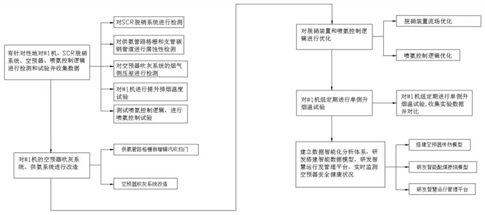
[0053] refer to Figure 1-2 , a method for predicting air preheater clogging, comprising the following steps:

[0054] Test #1 unit, SCR denitrification system, air preheater, and ammonia injection control logic through experiments to collect data;

[0055] By transforming the single-pass soot blower into a double-pass soot blower, and installing steam pipes for blowing scale at each ammonia supply grid, the air preheater soot blowing system and ammonia supply system of #1 machine can be realized. adjustment work;

[0056] The denitrification reaction in the process of air flow is fully realized through the guide plate set on the top of the denitrif...


PUM


Abstract

The invention discloses a method for predicting blockage of an air pre-heater. The method comprises the following steps: detecting and testing a # 1 machine, an SCR (Selective Catalytic Reduction) denitration system, the air pre-heater and ammonia injection control logic in a targeted manner, and collecting data; transforming a one-way soot blower into a two-way soot blower, arranging a steam pipe for purging oxide skin at each ammonia supply grid, and transforming an air pre-heater soot blowing system and an ammonia supply system of the # 1 machine. Units are detected and tested in a targeted mode, data is collected, the system is optimized and improved, data monitoring, a heat transfer algorithm, ammonium bisulfate characteristics and other elements are effectively combined, an air pre-heater heat transfer model is built, generation of ammonium bisulfate of the air pre-heater in the deep peak regulation period is effectively avoided. Blockage degree of the air pre-heater is accurately predicted by analyzing parameter changes, an operator is assisted to take prevention and control measures in advance, ammonium bisulfate blockage of the air pre-heater is avoided, and safe and economical operation of units is guaranteed.

Description

technical field [0001] The invention relates to the technical field of thermal power generation, in particular to a method for predicting air preheater clogging. Background technique [0002] A large number of thermal power units across the country have undergone ultra-clean emission transformation to meet the new environmental protection emission standards. However, while each thermal power unit is performing ultra-clean operation, air preheater clogging occurs to varying degrees. The reason for the blockage is: no A large amount of ammonia gas participating in the reaction increases, and the escaping ammonia gas reacts with SO3 in the flue gas to form ammonium bisulfate. The liquid ammonium bisulfate is extremely viscous and easily sticks to the fly ash in the flue gas, which is produced in the air preheater. Accumulated blockage will affect the output of the unit. [0003] Under ultra-clean operating conditions, more and more thermal power units are troubled by air prehe...

Claims


Application Information

Patent Timeline
Patent Type & Authority Applications(China)
IPC IPC(8): G06F30/20F23J3/00G06F113/08G06F119/08
CPCG06F30/20F23J3/00G06F2113/08G06F2119/08
Inventor 陈筑王海彬赵新飞李林王建冯晨李前胜姜彦辰韩旭王宁徐仁博戴润泽纪东阳蒋尚峰刘广鹏
Owner HUANENG POWER INTERNATIONAL
Learn More