Underwater cable duct bank laying structure

A technology for underwater cables and cable pipes, which is applied to underwater structures, cable installation, infrastructure engineering, etc. The effect of environmental improvement, short construction period and improved construction conditions

Pending Publication Date: 2022-02-11
浙江省水利水电勘测设计院有限责任公司
View PDF0 Cites 0 Cited by
  • Summary
  • Abstract
  • Description
  • Claims
  • Application Information

AI Technical Summary

Problems solved by technology

[0002] In water conservancy and hydropower projects, the cable pipe laying structure is an indispensable structure. The cable pipe is often buried in the cable channel of the traffic bridge when crossing the water system. When the traffic bridge channel is inconvenient to arrange the cable pipe, the river is often used Bottom or river bottom laying methods, laying construction methods include pipe jacking, dragging pipes and open-cut buried pipes; when water conservancy projects are constructed across water systems, cofferdams are often used to create dry construction conditions, and the construction of open-cut buried pipes in foundation pits is simple and requires less investment. The cost is low, but the vertical direction of the pipeline is usually high on both sides of the river and low in the middle. Once water flows into or seeps into the cable tube during construction or operation, it will be difficult to discharge. The long-term soaking of the cable in water will affect the service life of the cable, and it is difficult to repair and replace.

Method used


Image

  • Underwater cable duct bank laying structure
  • Underwater cable duct bank laying structure
  • Underwater cable duct bank laying structure

Examples


Embodiment Construction

[0025] The present invention will be further described below in conjunction with the accompanying drawings and embodiments.

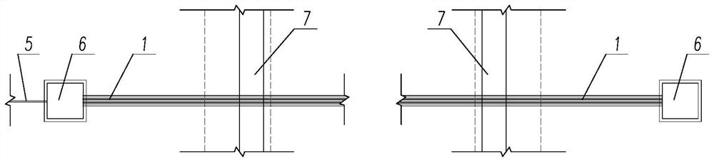
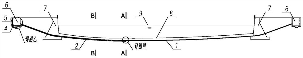
[0026] Such as Figure 1 to Figure 7 As shown, the present invention proposes an underwater cable pipe laying structure, which utilizes the dry land cut and buried pipe construction created by the cofferdam, including cable pipe 1, leakage drainage equipment 2, water level monitoring equipment 3, drainage pump 4, Exhaust pipeline 5 and cable well 6 etc. The cable pipe 1 is laid along the ground line 8 at the bottom of the river, and extends to both banks, passes through the revetment retaining wall 7 and extends into the cable shaft 6; the cable pipe 1 includes a cable pipe 11, an outsourcing reinforced concrete 12, a plain concrete cushion 13, Different diameter tee 14, cable 15 and caulking structure 16.

[0027] The lowest point of the cable pipe 1 is connected to the leakage drainage equipment 2. The leakage drainage equipment 2 includes a drainag...


PUM


Abstract

The invention discloses an underwater cable duct bank laying structure. The underwater cable duct bank laying structure comprises a cable duct bank, leakage drainage equipment, water level monitoring equipment, a drainage pump and a cable well. The cable duct bank is laid along the river bottom, a drainage pipe at the lowest point of the cable duct is connected to a lower leakage water-collecting well, and the bottom of the leakage water-collecting well is connected with a drainage pipe header pipe and the water level monitoring equipment. The drainage pipe header pipe is led into a shoreside cable well along with the cable duct bank to be connected with the drainage pump and is discharged to an external drainage system. The pressure gauge type water level gauge is arranged at the bottom of the leakage water-collecting well to monitor leakage water level to control opening and closing of the drainage pump. According to the water level gauge and the water level gauge power line, the water level gauge power line can be pulled by gravity to complete installation and replacement of the water level gauge. A gap between the end part of the cable duct and the cable is plugged by a caulking structure, and a breather pipe is embedded to ensure the balance of air pressure inside and outside the cable duct. According to the invention, the cable operation environment is improved, the construction period is saved, the safety is guaranteed, and the overall investment increase is less.

Description

technical field [0001] The invention relates to a cable pipe laying structure, in particular to a cable pipe laying structure with a drainage system and a cross-underpassing water system. Background technique [0002] In water conservancy and hydropower projects, the cable pipe laying structure is an indispensable structure. The cable pipe is often buried in the cable channel of the traffic bridge when crossing the water system. When the traffic bridge channel is inconvenient to arrange the cable pipe, the river is often used Bottom or river bottom laying methods, laying construction methods include pipe jacking, dragging pipes and open-cut buried pipes; when water conservancy projects are constructed across water systems, cofferdams are often used to create dry construction conditions, and the construction of open-cut buried pipes in foundation pits is simple and requires less investment. The cost is low, but the vertical direction of the pipeline is usually high on both si...

Claims


Application Information

Patent Timeline
Patent Type & Authority Applications(China)
IPC IPC(8): E02D29/12E02D29/14E02D19/04E02D29/00E02D19/10E02D19/20E02D31/02E02D29/05E02B3/10H02G9/02
CPCE02D29/12E02D29/14E02D19/04E02D29/06E02D19/10E02D19/20E02D31/02E02D29/05E02B3/10H02G9/02
Inventor 刘大康赖勇胡勇陈知渊戴邦国
Owner 浙江省水利水电勘测设计院有限责任公司
Why Eureka
Try Eureka