
L-type base region SiC MOSFET cellular structure, device and manufacturing method

A base, L-type technology, used in semiconductor/solid-state device manufacturing, electrical components, semiconductor devices, etc., can solve problems such as limiting operating frequency and system efficiency, serious electric field concentration effect, and inability to coat P-type base regions. Achieve the effect of reducing on-resistance, reducing the peak value of the electric field, and avoiding premature breakdown

Active Publication Date: 2022-02-08
北京昕感科技有限责任公司
View PDF4 Cites 4 Cited by
  • Summary
  • Abstract
  • Description
  • Claims
  • Application Information

AI Technical Summary

Problems solved by technology

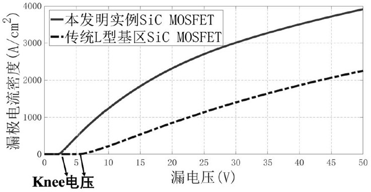
However, the traditional L-shaped base trench SiC MOSFET structure will add a section of lateral channel and compress the width of the current path, resulting in an increase in on-resistance, and knee voltage may appear in the output characteristic curve
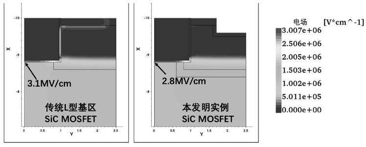
At the same time, the P-type base region cannot cover the middle of the bottom of the gate trench, where the electric field concentration effect is still serious, and the gate-to-drain capacitance is high, which limits the improvement of operating frequency and system efficiency

Method used


Image

  • L-type base region SiC MOSFET cellular structure, device and manufacturing method
  • L-type base region SiC MOSFET cellular structure, device and manufacturing method
  • L-type base region SiC MOSFET cellular structure, device and manufacturing method

Examples


Embodiment Construction

[0041] Embodiments of the present invention will be described in detail below with reference to the accompanying drawings. In the various drawings, the same elements are denoted by the same reference numerals, and various parts in the drawings are not drawn to scale. Also, some well-known parts may not be shown. For the sake of simplicity, the semiconductor structure obtained after several steps can be described in one figure.

[0042]It should be understood that when describing the structure of a device, when a layer or a region is referred to as being "on" or "over" another layer or another region, it may mean being directly on another layer or another region, or Other layers or regions are also included between it and another layer or another region. And, if the device is turned over, the layer, one region, will be "below" or "beneath" the other layer, another region.

[0043] The terms used in the present invention are for describing specific embodiments only, and are n...


PUM


Abstract

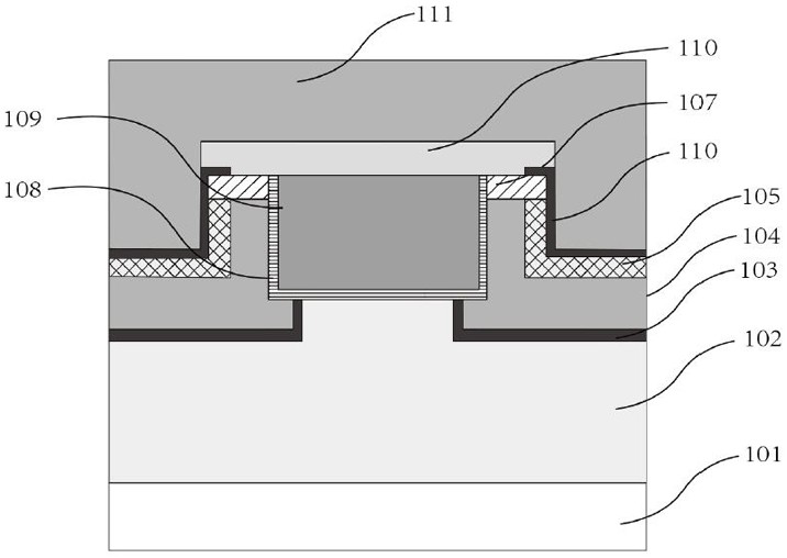
The invention discloses an L-type base region SiC MOSFET cellular structure, a device and a manufacturing method. The L-type base region SiC MOSFET cellular structure comprises an N++ SiC substrate, an N- SiC drift layer, a P-type base region and an N+ source region. The N- SiC drift layer is located above the N++ SiC substrate, a source trench and a gate trench are formed in the N- SiC drift layer, and a gate dielectric layer and a gate electrode are arranged in the gate trench. The P-type base region and the N+ source region are positioned on the N- SiC drift layer between the source trench and the gate trench and are arranged from bottom to top, an N-type current conducting layer is arranged between the P-type base region and the N- SiC drift layer, and a source N+ ohmic contact region is arranged between the P-type base region and the source trench. According to the device structure, the on resistance and the gate-drain capacitance can be further reduced, the conduction loss and the switching loss can be reduced, the working frequency can be improved, the premature breakdown of the P-type base region can be avoided, and the reliability of the device can be ensured.

Description

technical field [0001] The invention relates to the technical field of transistor electronic device preparation, in particular to a SiC MOSFET cell structure, a device and a manufacturing method thereof. Background technique [0002] Silicon carbide (SiC) is a third-generation semiconductor material. The band gap is three times that of silicon (Si), the first-generation semiconductor material, the critical breakdown electric field strength is ten times that of Si, and the electron saturation drift rate is Si 2 times that of Si, and the thermal conductivity is 3 times that of Si, which makes SiC power semiconductor devices, especially SiC MOSFETs, have significant performance advantages such as high temperature, high voltage, high frequency, and high efficiency, and have broad application prospects in power electronic systems. [0003] A key challenge for SiC MOSFETs is in SiC / SiO 2 There are interface states and the scattering effect of trapped charges on electrons at the i...

Claims


Application Information

Patent Timeline
Patent Type & Authority Applications(China)
IPC IPC(8): H01L29/08H01L21/336H01L29/78
CPCH01L29/0865H01L29/66068H01L29/7816
Inventor 张文渊马鸿铭王哲
Owner 北京昕感科技有限责任公司
Learn More