
Metal grid structure, touch display device and mobile terminal

A technology of metal grid and touch display, which is applied in the direction of instruments, electrical digital data processing, and input/output process of data processing, etc. It can solve the problems of high reflectivity, thin copper film, thick substrate, etc., and achieve economical improvement. properties and conductivity, and the effect of thinning the overall thickness

Active Publication Date: 2022-02-08
MICRON OPTOELECTRONICS CO LTD
View PDF12 Cites 0 Cited by
  • Summary
  • Abstract
  • Description
  • Claims
  • Application Information

AI Technical Summary

Problems solved by technology

[0011] The purpose of the present invention is to provide a capacitive touch screen, which can solve the problems of thin copper film, thick base material, low transmittance and high reflectivity in the existing touch screen, effectively improve the economy and conductivity of the product, and realize the light and thin touch screen change

Method used


Image

  • Metal grid structure, touch display device and mobile terminal
  • Metal grid structure, touch display device and mobile terminal
  • Metal grid structure, touch display device and mobile terminal

Examples


Embodiment Construction

[0029] It should be noted that, in the case of no conflict, the embodiments in the present application and the features in the embodiments can be combined with each other. The present invention will be described in detail below with reference to the accompanying drawings and examples.

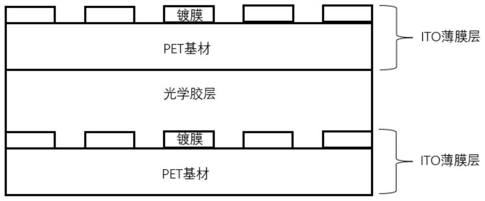
[0030] An embodiment of the present invention provides a metal grid structure for a capacitive touch screen. FIG. 1 is a schematic diagram of a metal grid structure for a capacitive touch screen according to an embodiment of the present invention. Such as figure 1 As shown, the metal grid structure 100 includes: a first metal grid layer 101, a first coating layer 102, a first optical adhesive layer 103, a second metal grid layer 104 and a second coating layer 105 arranged in sequence , wherein the first coating layer 102 is coated on the first metal grid layer 101, the thickness of the first coating layer 102 is smaller than the thickness of the first metal grid layer 101, and the second coat...


PUM

PropertyMeasurementUnit
thicknessaaaaaaaaaa
thicknessaaaaaaaaaa
thicknessaaaaaaaaaa

Abstract

The invention discloses a metal grid structure for a capacitive touch screen, a touch display device and a mobile terminal. The metal grid structure comprises a first metal grid layer, a first coating layer, a first optical adhesive layer, a second metal grid layer and a second coating layer which are arranged in sequence, the first metal grid layer is coated with the first coating layer, the thickness of the first coating layer is smaller than that of the first metal grid layer, the second metal grid layer is coated with the second coating layer, and the thickness of the second coating layer is smaller than that of the second metal grid layer. The structure can solve the problems that an existing touch screen is thin in copper film, thick in base material, low in transmittance and large in reflectivity, and the economical efficiency and the conductivity of products are effectively improved. Compared with an existing metal grid structure, due to the fact that no polymer base material exists, the overall thickness is obviously reduced, the total transmittance of the thin film is improved, and the touch screen is light and thin.

Description

technical field [0001] The invention relates to the field of optical films, in particular to a metal grid structure for a capacitive touch screen, a touch display device and a mobile terminal. Background technique [0002] With the development of touch technology, traditional resistive touch screens are gradually replaced by capacitive touch screens that are thinner and have better touch performance. In many capacitive touch screens, metal mesh has been widely used in the industry. [0003] At present, there are two metal grid technologies widely used in the industry: copper metal grid technology and silver halide nanoparticle metal grid technology. Both of these two technologies make metal grid electrodes on polyester resin (PET) substrates, and then use OCA film bonding technology to bond PET transparent conductive films on the glass cover to form capacitive touch screens with GFF or GF2 structure. [0004] Such as figure 1 As shown, the GFF structure includes an upper ...

Claims


Application Information

Patent Timeline
Patent Type & Authority Applications(China)
IPC IPC(8): G06F3/041G06F3/044
CPCG06F3/0412G06F3/0445G06F3/0446G06F2203/04103G06F3/0443G06F2203/04112
Inventor 苏伟叶宗和
Owner MICRON OPTOELECTRONICS CO LTD
Learn More