


Quick Research
Generate reliable direction feasibility study reports for your R&D in just a few steps.

Technical Q&A
Discover and master advanced knowledge NOW. Basics, ideas, possibilities, all at once.

Find Solutions
As an expert in R&D theories, this can generate solutions to your technical problems instantly.

Evaluate Feasibility
Analyze your overall solution with one click, know your potential R&D risks in advance.

Monitor Landscape
Get weekly tech updates, stay abreast of the latest tech innovations and key insights.
Water turbine runner positioning, assembling and welding method based on wedge-shaped auxiliary devices
A technology for auxiliary devices and water turbines, applied in auxiliary devices, auxiliary welding equipment, welding/cutting auxiliary equipment, etc., can solve the problems of assembly, poor positioning accuracy, reduce labor intensity, reduce production costs, etc., and achieve compensation for welding shrinkage, The effect of simplifying the assembly process and improving the accuracy of assembly and welding
- Summary
- Abstract
- Description
- Claims
- Application Information
AI Technical Summary
Problems solved by technology
Method used
Image

Examples
Embodiment 1
[0046] This embodiment discloses a water turbine runner positioning and welding method based on a wedge-shaped auxiliary device 4. As a basic embodiment of the present invention, the positioning and welding of the runner is carried out in reverse order, including component processing, wedge-shaped installation Auxiliary device 4, component positioning and component assembly.
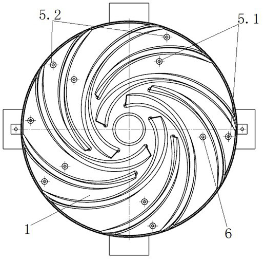
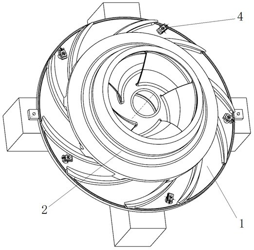
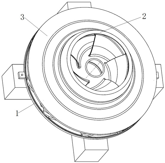
[0047] Said component processing: set a unified processing standard by a numerical control machine tool, and process all the components of the runner under the processing standard, and the components include the upper crown blisk 1, the inner ring blisk 2 and the outer ring blisk 3; During the processing of each component, a number of pin holes for assembly are processed on the upper crown blisk 1, positioning pins are processed on the inner ring blisk 2 and the outer ring blisk 3, and are marked and recorded or stamped with a serial number. way, so that the pin holes correspond to the positioning pins o...
Embodiment 2
[0060] This embodiment discloses a positioning and welding method for a turbine runner based on a wedge-shaped auxiliary device 4. As a preferred embodiment of the present invention, the positioning and welding of the runner is carried out in reverse order, including component processing and wedge-shaped auxiliary installation. Device 4, component positioning and component assembly.
[0061] Component processing: set a unified processing standard through the CNC machine tool, and process all the components of the runner under the processing standard. In the process of component processing, a number of pin holes for assembly are processed on the upper crown blisk 1, positioning pins are processed on the inner ring blisk 2 and the outer ring blisk 3, and by marking records or stamping numbers, Make the pin holes correspond to the positioning pins one by one.
[0062] Install wedge-shaped auxiliary device 4: Prepare a number of wedge-shaped auxiliary devices 4. When processing t...
Embodiment 3
[0074] This embodiment discloses a positioning and welding method for a turbine runner based on a wedge-shaped auxiliary device 4. As a preferred embodiment of the present invention, the positioning and welding of the runner is carried out in reverse order, including component processing and wedge-shaped auxiliary installation. Device 4, component positioning and component assembly.
[0075]Said component processing: set a unified processing standard through the numerical control machine tool, and process all the components of the runner under the processing standard, including the upper crown blisk 1, the inner ring blisk 2 and the outer ring blisk 3; During the crown blisk 1 period, in the flow channel processing process of the upper tube blisk, through three-dimensional modeling and numerical control programming, a number of pin holes for assembly are processed on the upper blisk 1, and reserved in the flow channel for installing wedges. The boss structure 5 of the auxiliar...
PUM
| Property | Measurement | Unit |
|---|---|---|
| Slope angle | aaaaa | aaaaa |
Abstract
Description
Claims
Application Information
 - R&D Engineer
- R&D Manager
- IP Professional
- Industry Leading Data Capabilities
- Powerful AI technology
- Patent DNA Extraction
Browse by: Latest US Patents, China's latest patents, Technical Efficacy Thesaurus, Application Domain, Technology Topic, Popular Technical Reports.
© 2024 PatSnap. All rights reserved.Legal|Privacy policy|Modern Slavery Act Transparency Statement|Sitemap|About US| Contact US: help@patsnap.com