Multi-band resonant frequency tracking circuit and method applied to ultrasonic machining

A resonant frequency and tracking circuit technology, applied in frequency measurement devices and other directions, can solve the problems of speeding up the resonant frequency tracking speed, poor flexibility, inability to distinguish whether the resonant frequency is the forward resonant frequency or the reverse resonant frequency, etc., to achieve a simple and fast implementation process. , Improve the effect of fast and accurate tracking

Pending Publication Date: 2022-01-28
HANGZHOU DIANZI UNIV
View PDF0 Cites 0 Cited by
  • Summary
  • Abstract
  • Description
  • Claims
  • Application Information

AI Technical Summary

Problems solved by technology

[0004]However, there is a limitation in the frequency adjustment range of PLL technology. For different types of piezoelectric transducers with different resonant frequencies, it is necessary to adjust the hardware parameters of PLL to Change the range of output frequency, so the use of phase-locked loop technology to achieve resonance frequency tracking has disadvantages such as poor flexibility, poor structure, and high cost; the composite frequency tracking method can speed up the resonance frequency tracking to a certain extent, but the composite frequency tracking method also exists A certain defect, that is, it only uses the phase difference of zero to judge whether to track the resonance frequency, but the piezoelectric transducer actually has positive and negative resonance frequencies, at the positive resonance frequency point Fs and the reverse resonant frequency point Fp, their phases are both zero, at this time the composite resonant frequency tracking strategy will not be able to distinguish whether the tracked resonant frequency is forward resonant frequency or reverse resonant frequency; the maximum current The biggest disadvantage of the method of tracking the resonant frequency is that the tracking is slow. When the load changes suddenly, the resonant frequency tracking often cannot keep up with the change of the load. Therefore, the maximum current method to track the resonant frequency is not suitable for application scenarios with severe load changes; the fuzzy PI strategy The disadvantage of the resonant frequency tracking method is that under load conditions, when the impedance characteristics of the piezoelectric transducer vary greatly, since the fuzzy PI only uses the phase difference as the control signal, the fuzzy PI cannot distinguish the resonant frequency being tracked as a positive resonance frequency or anti-resonant frequency

Method used


Image

  • Multi-band resonant frequency tracking circuit and method applied to ultrasonic machining
  • Multi-band resonant frequency tracking circuit and method applied to ultrasonic machining
  • Multi-band resonant frequency tracking circuit and method applied to ultrasonic machining

Examples


Embodiment 1

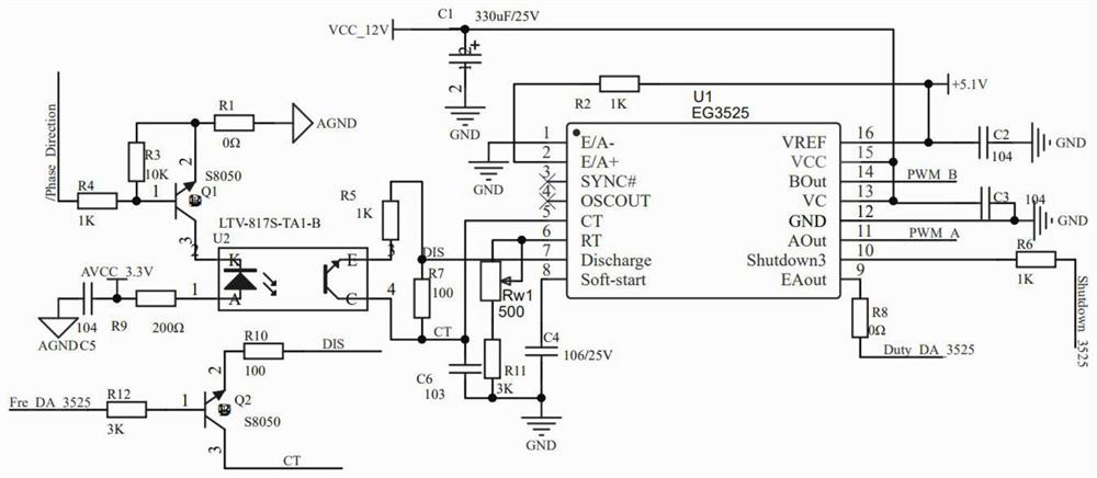
[0036] This embodiment provides a multi-band resonant frequency tracking circuit applied to ultrasonic processing, such as figure 1 As shown, it includes an output current voltage phase difference direction detection circuit and a multi-band resonance frequency tracking circuit, the detection signal output end of the output current voltage phase difference direction detection circuit is connected to the signal input end of the multi-band resonance frequency tracking circuit,

[0037] The signal input end of the multi-band resonance frequency tracking circuit includes a PWM control chip U1, a resistor R1, a resistor R2, a resistor R3, a resistor R4, a resistor R5, a resistor R6, a resistor R8, a resistor R9, a resistor R10, a resistor R11, and a resistor R12 , transistor Q1, transistor Q2, sliding rheostat Rw1, optocoupler U2, capacitor C1, capacitor C2, capacitor C3, capacitor C4, capacitor C5, capacitor C6,

[0038] One end of the resistor R4 is connected to the detection sig...

Embodiment 2

[0050] This embodiment discloses a multi-band resonant frequency tracking method applied to ultrasonic processing, such as image 3 As shown, including the following cycle steps:

[0051] S1. Start the equipment, and the piezoelectric transducer works at normal frequency;

[0052] S2. Real-time detection of the voltage and current signals of the piezoelectric transducer circuit through the output current and voltage phase difference direction detection circuit;

[0053] S3. According to the detection result, the multi-band resonant frequency tracking circuit drives the piezoelectric transducer to adjust the frequency.

[0054] In the above technical scheme, it is assumed that t 1 The ultrasonic power supply works normally at the driving signal frequency f at all times, and the frequency tracking is good, while at t 2 At this time, the piezoelectric transducer begins to be affected by the outside world, and its characteristics change.

[0055] t 2 moment, when the system i...

Embodiment 3

[0065] The difference between this embodiment and Embodiment 2 is that in S2, a system detuning duration threshold is preset, and the maximum value of the time threshold is set to 20 ms.

[0066] In the above technical solution, the maximum range of the time threshold is set to 20ms. Because there is enough time to monitor the level signal, the judgment result of the system detuning state is more accurate, the error rate of detuning judgment is greatly reduced, and then the adjustment is made quickly, and then it turns into an overall stable state in a small vibration state.


PUM


Abstract

The invention discloses a multi-band resonant frequency tracking circuit applied to ultrasonic machining, which comprises an output current and voltage phase difference direction detection circuit and a multi-band resonant frequency tracking circuit, wherein the detection signal output end of the output current and voltage phase difference direction detection circuit is connected with the signal input end of the multi-band resonant frequency tracking circuit. By adopting the technical scheme, the system detuning condition is quickly judged through the current and voltage phase difference direction detection signal output by a D trigger in the SN74HC74D chip, and the dead zone resistance between a pin 5 and a pin 7 in the EG3525 chip can be changed in time according to the detuning degree of a piezoelectric transducer, so that the system driving frequency is changed to track the resonant frequency of the piezoelectric transducer, and rapid and accurate tracking is realized. The realization process of the circuit function is simple and rapid, and the capability of rapidly and accurately tracking the forward resonant frequency point of the piezoelectric transducer is improved.

Description

technical field [0001] The invention relates to the technical field of ultrasonic machine tools, in particular to a multi-band resonant frequency tracking circuit and method applied to ultrasonic processing. Background technique [0002] The piezoelectric transducer is the core component of the entire ultrasonic system. Under the excitation of the external high-frequency drive signal, the piezoelectric transducer produces vibrations at the same frequency. When the frequency of the driving signal is the same as the natural frequency of the piezoelectric transducer , the output vibration amplitude of the piezoelectric transducer is the largest. However, during the ultrasonic machining process, the resonance frequency of the piezoelectric transducer drifts due to the change of the external load force. Therefore, in the process of ultrasonic machining, it is necessary to continuously adjust the frequency of the driving signal to track the resonance frequency of the piezoelectri...

Claims


Application Information

Patent Timeline
Patent Type & Authority Applications(China)
IPC IPC(8): G01R23/02
CPCG01R23/02
Inventor 孔亚广陈张平唐西超邹洪波黄娜张帆赵晓东陈洪欢
Owner HANGZHOU DIANZI UNIV
Why Eureka
Try Eureka