
Washing equipment capable of rapidly dehydrating optical lens

A technology for optical lenses and washing equipment, applied in lighting and heating equipment, chemical instruments and methods, cleaning methods using liquids, etc., can solve the problems of low efficiency, slow drying speed, energy and efficiency, etc., to improve washing efficiency. , the effect of reducing cleaning costs

Active Publication Date: 2022-01-28
上饶市桐宇光电科技有限公司
View PDF5 Cites 1 Cited by
  • Summary
  • Abstract
  • Description
  • Claims
  • Application Information

AI Technical Summary

Problems solved by technology

[0002]The production process of optical lenses is: milling-finishing-polishing-cleaning-edging-coating-inking-gluing, cleaning is to polish the optical lenses The polishing powder on the surface is cleaned to prevent pressure. At present, two methods are generally used to clean the polished optical lens. The first is manual cleaning, and the second is ultrasonic cleaning. Manual cleaning requires more cost. Time and energy and efficiency are relatively slow, while ultrasonic cleaning costs are high, and whether it is manual cleaning or ultrasonic cleaning, it is necessary to quickly dehydrate and dry the optical lenses after cleaning, but after manual cleaning, the optical lenses are generally dried naturally. Dry, slow drying speed and low efficiency, and the existing ultrasonic cleaning equipment generally does not have the function of dehydration and drying, and cannot dehydrate and dry the cleaned optical lenses

Method used


Image

  • Washing equipment capable of rapidly dehydrating optical lens
  • Washing equipment capable of rapidly dehydrating optical lens
  • Washing equipment capable of rapidly dehydrating optical lens

Examples


Embodiment 1

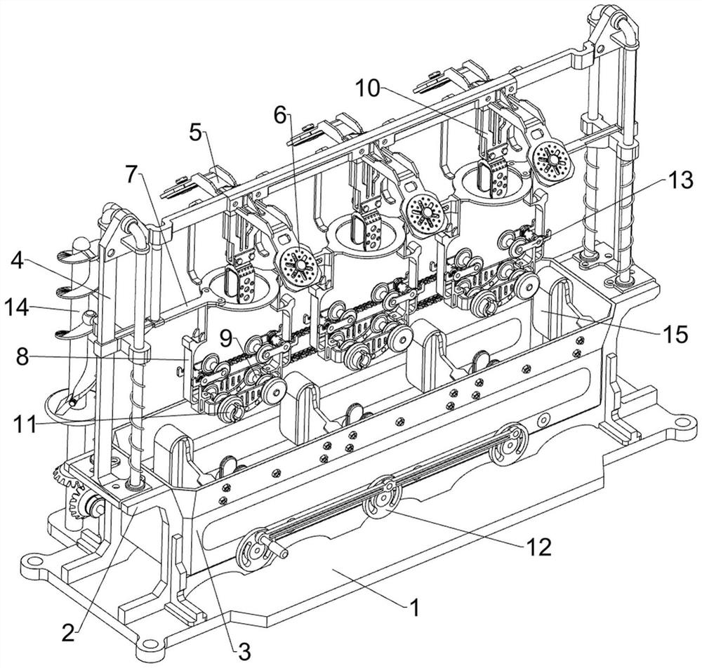
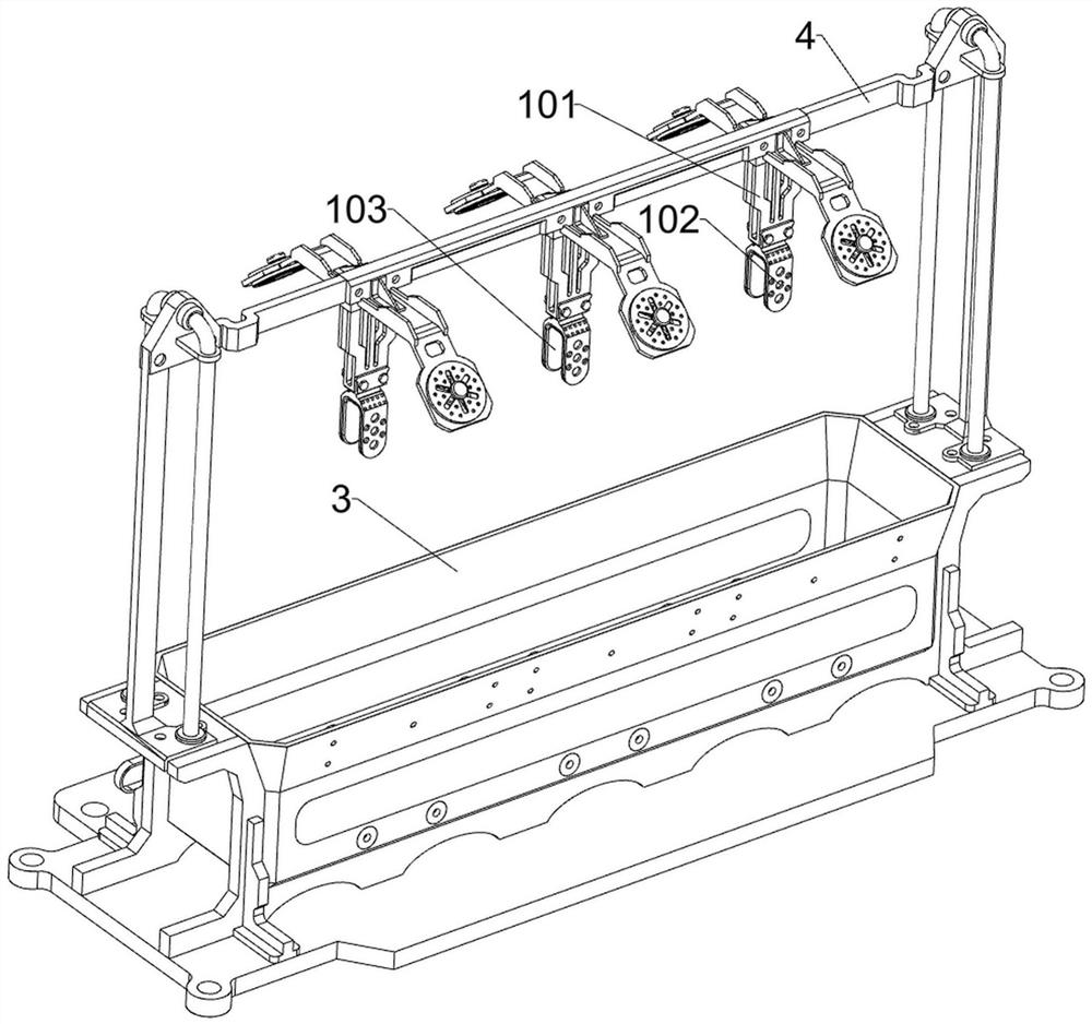
[0038] combine Figure 1-15 As shown, the present application provides a washing device capable of rapidly dehydrating optical lenses, including a base 1, a mounting base 2, a box body 3, a first fixing frame 4, a first mounting frame 5, a fan 6, a sliding frame 7, a second A connecting frame 8, a first limiting wheel 9, a second limiting wheel 91 and a drying assembly 10, the top of the base 1 is connected with a mounting seat 2, and the mounting seat 2 is connected with a box body 3, and the box body 3 is used to hold clean water and cleaning agent, the top of the mounting seat 2 is connected with the first mounting frame 4 by means of bolt connection, and the front and rear sides of the first mounting frame 4 are evenly spaced and connected with three first mounting frames 5 and six first mounting frames. 5 are equipped with fan 6, the fan 6 is used to dry the optical lens after washing, the middle part of the first fixed frame 4 is slidably connected with a sliding frame 7...


PUM


Abstract

The invention relates to washing equipment capable of rapidly dewatering optical lenses, which comprises a base, a mounting seat, a box body, a first fixing frame, first mounting frames, a fan, a sliding frame, a first connecting frame and the like, the top of the base is connected with the mounting seat, the box body is connected in the mounting seat, and the top of the mounting seat is connected with the first fixing frame; the front side and the rear side of the upper portion of the first fixing frame are evenly connected with the three first mounting frames at intervals, the fans are installed on the six first mounting frames, the sliding frame is slidably connected to the middle of the first fixing frame, and the three first connecting frames are evenly connected to the bottom of the sliding frame at intervals. The sliding frame is moved downwards, so that the first connecting frame drives the optical lens to enter the box body, clear water and a cleaning agent in the box body wash the optical lens, water on the optical lens can be blow-dried through a draught fan, the optical lens is made to make contact with a water absorption cotton block upwards, and the optical lens is made to rotate; and therefore, the water absorption cotton block can completely wipe water on the optical lens.

Description

technical field [0001] The invention relates to a washing device for optical lenses, in particular to a washing device capable of rapidly dehydrating optical lenses. Background technique [0002] The production process of optical lenses is: milling-finishing-polishing-cleaning-edging-coating-inking-gluing. Cleaning is to clean the polishing powder on the surface of the polished optical lens to prevent pressure. There are generally two ways to clean the final optical lens. The first is manual cleaning, and the second is ultrasonic cleaning. Manual cleaning takes more time and energy and is less efficient, while ultrasonic cleaning costs more. And whether it is manual cleaning or ultrasonic cleaning, it is necessary to quickly dehydrate and dry the cleaned optical lenses, but after manual manual cleaning, the optical lenses are generally dried naturally, the drying speed is slow and the efficiency is low, and the existing ultrasonic cleaning equipment Generally, it does not h...

Claims


Application Information

Patent Timeline
Patent Type & Authority Applications(China)
IPC IPC(8): B08B11/00B08B3/10B08B13/00F26B5/14F26B21/00
CPCB08B11/00B08B3/10B08B13/00F26B21/001F26B5/14
Inventor 徐雁
Owner 上饶市桐宇光电科技有限公司
Learn More