Circular vibrating screen lubricated by thin oil

A circular vibrating screen, thin oil lubrication technology, applied in the direction of lubricating parts, engine lubrication, lubricating oil control valve, etc. Easy maintenance, good lubrication and stable flow

Pending Publication Date: 2022-01-18
洛阳元耐机械有限公司
View PDF0 Cites 0 Cited by
  • Summary
  • Abstract
  • Description
  • Claims
  • Application Information

AI Technical Summary

Problems solved by technology

[0005] In order to make up for the deficiencies of the existing technology, the lubricating cavity of the existing vibrator has a small volume and no heat dissipation, and the existing vibrator has fewer lubricating points, which cannot be lubricated in time, and the friction heat generated by the friction pair cannot be taken away , large wear and easy loss, the invention proposes a thin oil lubricated circular vibrating screen

Method used


Image

  • Circular vibrating screen lubricated by thin oil
  • Circular vibrating screen lubricated by thin oil
  • Circular vibrating screen lubricated by thin oil

Examples


Embodiment

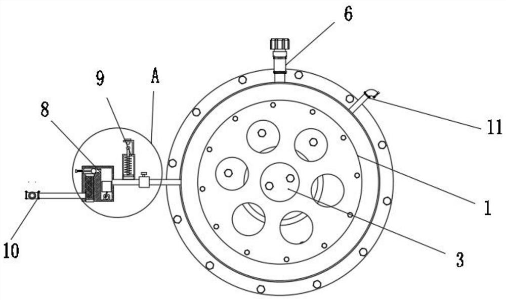
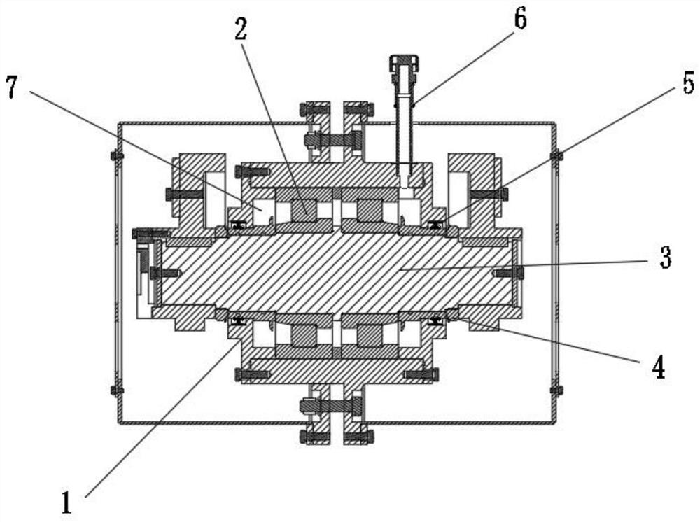
[0027] like Figure 1 to Figure 4 As shown, a thin oil lubricated circular vibrating screen according to the present invention includes an installation main body 1, a bearing 2, a main shaft 3, a round nut 4, a lip seal 5, an exhaust pipe 6, a lubricating inner cavity 7, and a Pressure component 8, release component 9, oil discharge pipe 10 and oil inlet pipe 11; bearing 2 is installed inside the installation body 1, the main shaft 3 is installed inside the installation main body 1, the main shaft 3 runs through the inside of the bearing 2, the installation body 1 and the main shaft 3 The splicing port is filled with a lip seal 5, the two ends of the installation body 1 are sealed with round nuts 4, a lubricating inner cavity 7 is formed between the installation body 1 and the main shaft 3, and oil drain pipes 10 are respectively installed on the installation body 1 And the oil inlet pipe 11, the oil discharge pipe 10 is provided with a pressurizing assembly 8 and a release as...

Embodiment approach

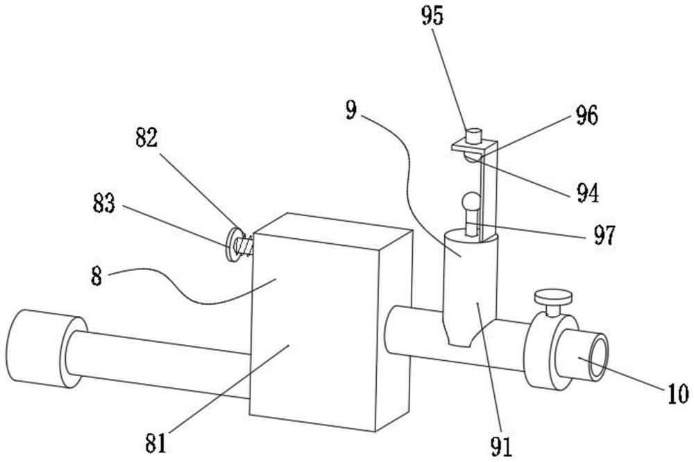
[0028] As an embodiment of the present invention, the pressurizing assembly 8 includes a pressurizing box 81, a first spring 82, a squeeze rod 83, a blocking ball 84, a filter chamber 85, a filter core 86, a stamping motor 87, a pull rod 88, a rotating Disc 89, piston cylinder 810 and stamping chamber 811, filter chamber 85 and stamping chamber 811 are arranged inside pressurized box 81, piston cylinder 810 is arranged inside stamping chamber 811, stamping motor is fixed on the bottom cavity wall of stamping chamber 811 87. A rotary disc 89 is installed on the rotating shaft of the stamping motor 87, and a connecting seat is installed at the bottom end of the piston cylinder 810. The bottom end of the pull rod 88 is mounted on the eccentric position of the end face of the rotary disc 89 through a pin shaft, and the top end of the pull rod 88 passes through The pin shaft is matched and installed in the connecting seat. The bottom of the filter chamber 85 is a hollow structure. T...


PUM


Abstract

The invention belongs to the technical field of vibration exciters, and particularly relates to a circular vibrating screen lubricated by thin oil. The circular vibrating screen comprises a mounting body, a bearing, a main shaft, a lip-shaped sealing ring, an exhaust pipe, a lubricating inner cavity, a pressurizing assembly, a releasing assembly, an oil discharging pipe and an oil inlet pipe, wherein the bearing is installed in the mounting body in a matched mode, the main shaft is installed in the mounting body, the main shaft penetrates through the interior of the bearing, and the lubricating inner cavity is formed between the mounting body and the main shaft. The thin oil is added through the oil inlet pipe in the using process and has the obvious advantages, a plurality of lubricating points which are widely distributed can be lubricated in time, meanwhile, friction heat generated by friction is taken away, and metal abrasive particles and other mechanical impurities on the friction surface are taken away and washed away along with flowing and circulation of oil, so that the purposes of good lubrication, friction reduction, abrasion reduction, consumption reduction of quick-wear parts, power consumption reduction and prolonging of the service life of equipment are achieved.

Description

technical field [0001] The invention belongs to the technical field of vibration exciters, in particular to a circular vibrating screen lubricated with thin oil. Background technique [0002] The exciter is a device attached to some machinery and equipment to generate excitation force. It is an important part that uses mechanical vibration. The exciter can make the excited object obtain a certain form and size of vibration, thereby vibrating the object. and strength tests, or to calibrate vibration testing instruments and sensors, and the vibrator can also be used as an excitation component to form a vibrating machine to realize the conveying, screening, compacting, forming and tamping of soil and gravel, etc. According to the different excitation types, the exciter is divided into inertial electric type, electromagnetic type, electro-hydraulic type, pneumatic type and hydraulic type. The exciter can produce unidirectional or multi-directional, simple harmonic or non-harmoni...

Claims


Application Information

Patent Timeline
Patent Type & Authority Applications(China)
IPC IPC(8): F16C37/00F16N7/38F16N23/00F16N29/04F16N31/00F16N39/06B07B1/28B07B1/46
CPCF16C37/007F16N7/38F16N23/00F16N29/04F16N31/00F16N39/06B07B1/28B07B1/46F16N2210/14F16N2260/08F16N2260/14
Inventor 李垂海丁亮亮
Owner 洛阳元耐机械有限公司
Why Eureka
Try Eureka