Foaming process and device for EVA shoe material production
A foaming device and shoe material technology, which is applied in the field of EVA shoe material foaming, can solve the problems that the blank material cannot meet the foaming requirements, the health and safety hazards of the staff, and the accuracy cannot be guaranteed, etc., and achieve simple structure, reduce manpower consumption, The effect of reducing physical exertion
- Summary
- Abstract
- Description
- Claims
- Application Information
AI Technical Summary
Problems solved by technology
Method used
Image
Examples
Embodiment 1
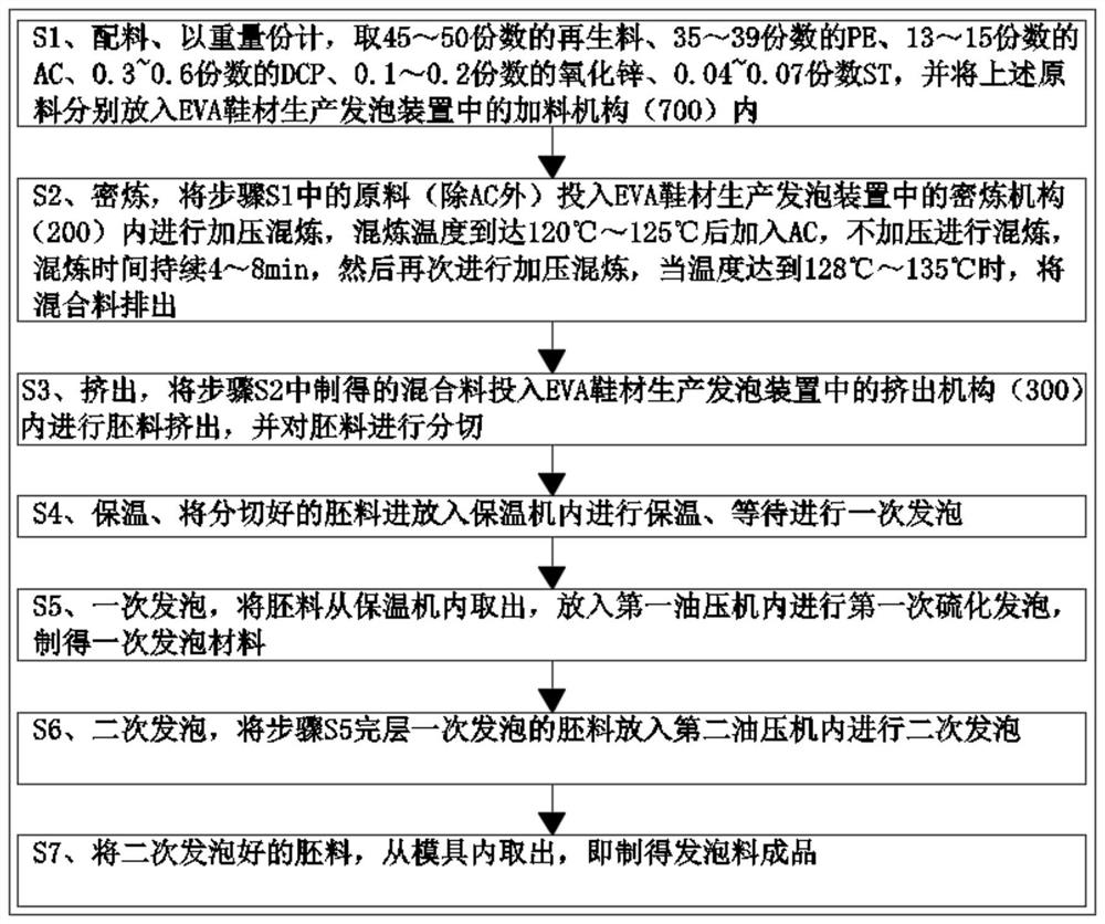
[0054] like figure 1 Shown, a kind of EVA shoe material production foaming process provided by the invention specifically comprises the following steps:
[0055] S1. Ingredients, in parts by weight, 45-50 parts of recycled materials, 35-39 parts of PE, 13-15 parts of AC, 0.3-0.6 parts of DCP, 0.1-0.2 parts of oxidation Zinc, 0.04 ~ 0.07 parts ST, and put the above-mentioned raw materials into the feeding mechanism 700 in the foaming device for EVA shoe material production;
[0056] S2, internal mixing, put the raw materials (except AC) in step S1 into the internal mixing mechanism 200 of the EVA shoe material production foaming device for pressurized mixing, and add AC after the mixing temperature reaches 120°C-125°C, Mixing without pressure, the mixing time lasts for 4-8 minutes, and then pressurized mixing again, when the temperature reaches 128 ° C ~ 135 ° C, the mixture is discharged;
[0057] S3, extrude, put the mixed material prepared in the step S2 into the extrusion...
Embodiment 2
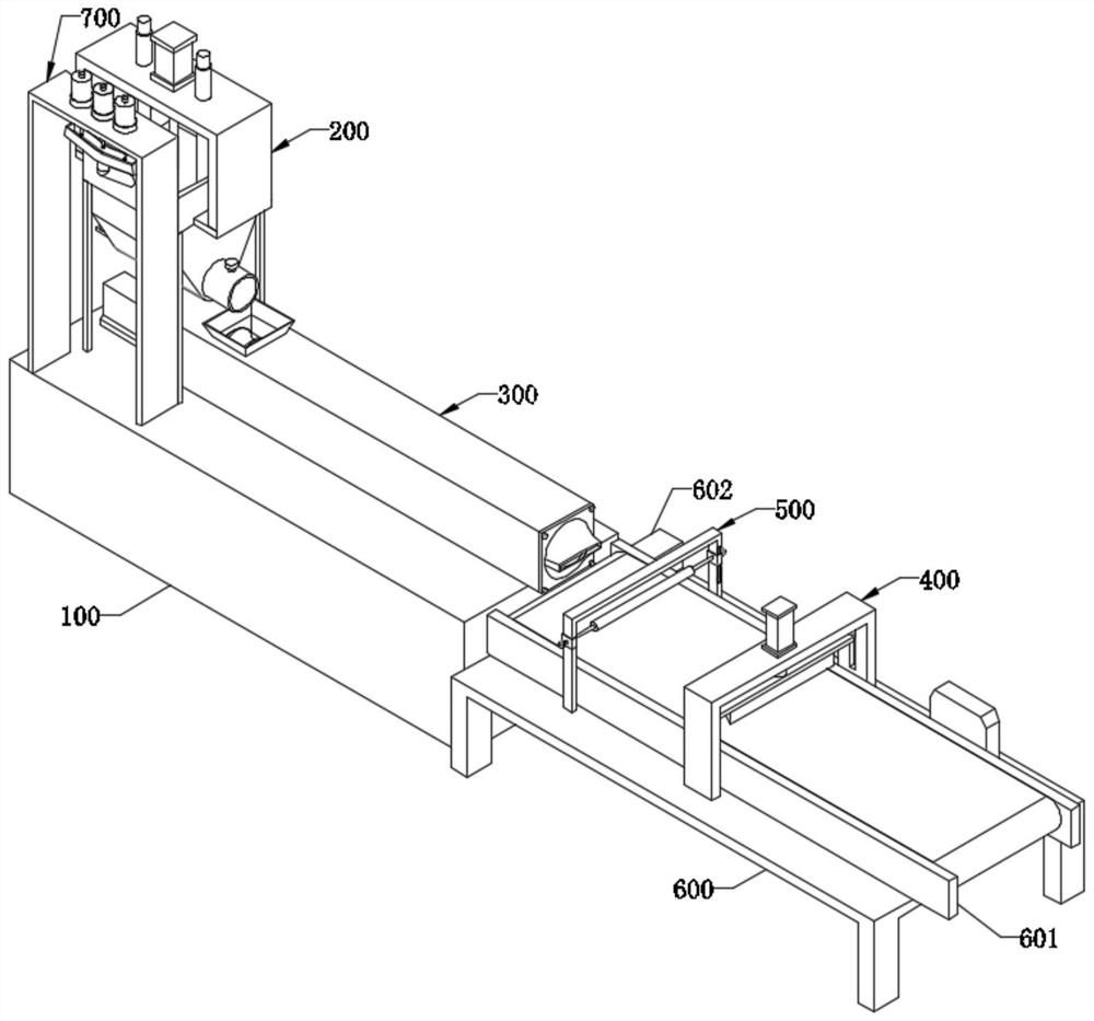
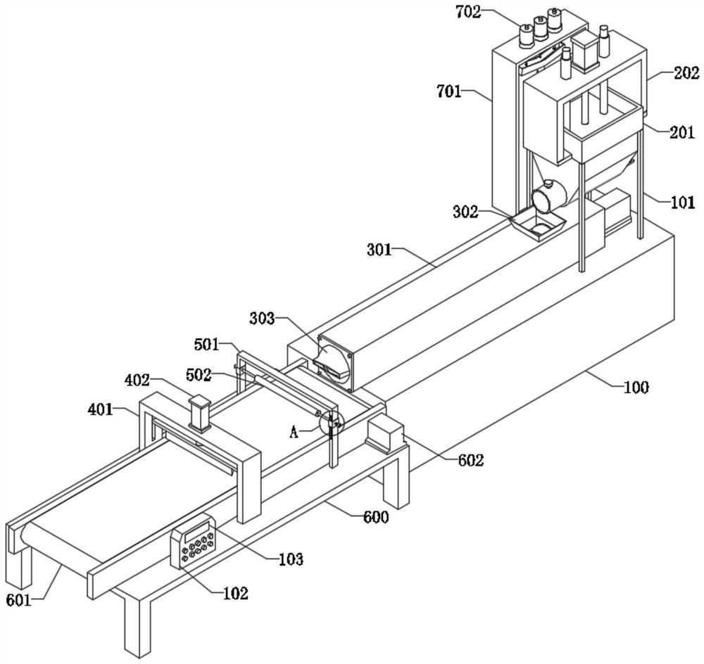
[0065] like Figure 2-Figure 9 As shown, a foaming device for EVA shoe material production provided by the present invention includes a base 100, a fixed frame 600, a mixing mechanism 200, an extrusion mechanism 300, a transmission assembly and a cutting mechanism 400;
[0066] Wherein, the internal mixing mechanism 200 is composed of a banbury box 201, a kneading motor 1 206, a kneading motor 2 207, an electric cylinder 1 212, and a briquetting block 215. 206 and kneading motor two 207 are all fixed on the side of mixing box 201, and kneading motor one 206 is positioned at the top of kneading motor two 207, and the rotating shaft of kneading motor one 206 and the rotating shaft of kneading motor two 207 are all fixedly connected with rotating shaft 208, rotates One end of the shaft 208 rotates through one side of the mixing box 201 and extends into the inside of the mixing box 201. The rotating shaft 208 is fixedly connected with a spiral blade 209, and the outer wall of the ...
Embodiment 3
[0074] The difference between this embodiment and Embodiment 2 is that a feeding mechanism 700 is provided on the top of the base 100, and the feeding mechanism 700 includes a mounting frame 701, and a plurality of bearing seats 704 are fixedly installed on the top of the mounting frame 701, and the bearing seats 704 A load cell 706 is arranged at the bottom of the interior, and a material holding tank 702 is arranged on the load sensor 706. The bottom of the material holding tank 702 is connected with a feeding pipe 703, and the lower end of the feeding pipe 703 runs through the top of the mounting frame 701 and extends into the mounting frame. The inner side of 701, the lower end of the feeding pipe 703 is provided with a feeding valve 705, the top of the fixed frame 600 is fixedly connected with a control box 102, the inside of the control box 102 is fixedly equipped with a PLC controller, the input end of the PLC controller is connected with the weighing The sensor 706 is e...
PUM
 Abstract
Description
Claims
Application Information
 - R&D
- Intellectual Property
- Life Sciences
- Materials
- Tech Scout
- Unparalleled Data Quality
- Higher Quality Content
- 60% Fewer Hallucinations
Browse by: Latest US Patents, China's latest patents, Technical Efficacy Thesaurus, Application Domain, Technology Topic, Popular Technical Reports.
© 2025 PatSnap. All rights reserved.Legal|Privacy policy|Modern Slavery Act Transparency Statement|Sitemap|About US| Contact US: help@patsnap.com


