Eureka AIR delivers breakthrough ideas for toughest innovation challenges, trusted by R&D personnel around the world.

Bottom plate wax mold structure and forming method of directional solidification shell bottom plate

A technology of directional solidification and molding methods, applied in the direction of casting mold components, casting molding equipment, casting molds, etc., to achieve the effects of preventing shrinkage deformation, good buffer support, and preventing unevenness of the bottom surface

Active Publication Date: 2022-01-14
CHINA HANGFA SOUTH IND CO LTD
View PDF8 Cites 3 Cited by
  • Summary
  • Abstract
  • Description
  • Claims
  • Application Information

AI Technical Summary

Problems solved by technology

[0004] The present invention provides a base plate wax mold structure and a forming method for a directionally solidified shell base plate to solve the above-mentioned shortcomings in the prior art

Method used


Image

  • Bottom plate wax mold structure and forming method of directional solidification shell bottom plate
  • Bottom plate wax mold structure and forming method of directional solidification shell bottom plate
  • Bottom plate wax mold structure and forming method of directional solidification shell bottom plate

Examples


Embodiment Construction

[0037] The embodiments of the present invention will be described in detail below with reference to the accompanying drawings, but the present invention can be implemented in various ways defined and covered below.

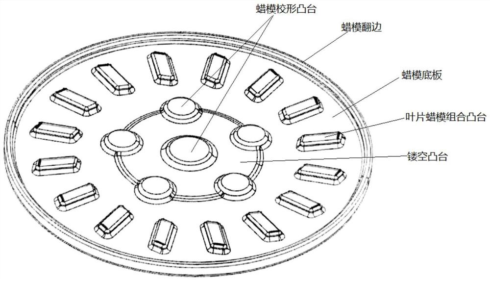
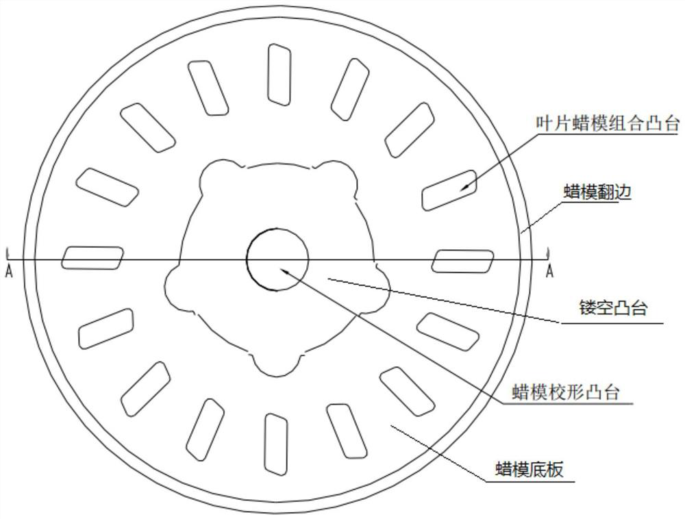
[0038] Such as Figure 1 to Figure 3 As shown, the preferred embodiment of the present invention provides a base plate wax pattern structure, the base plate wax pattern structure is used for the molding of directionally solidified shell bottom plate, and it comprises wax pattern bottom plate, wax pattern flanging, blade wax pattern combination boss 1. Wax mold shaping bosses and hollow bosses, the wax mold bottom plate is flat and disc-shaped, used to form the plane of the directionally solidified shell bottom plate, and the wax mold flanging is arranged on the edge of the wax mold bottom plate along the circumferential direction Above, the inner diameter surface of the wax pattern flanging is used to form the circumference of the directionally solidified shell bo...


PUM

PropertyMeasurementUnit
thicknessaaaaaaaaaa

Abstract

The invention discloses a bottom plate wax mold structure and a forming method of a directional solidification shell bottom plate. The bottom plate wax mold structure is characterized in that a plurality of annularly distributed blade wax mold combination bosses are arranged on a flat disc-shaped wax mold bottom plate, and therefore welded and fixed on a plurality of blade wax molds when a module is assembled into a tree; and a welding seam is moved out of a plane of the wax mold bottom plate, so that the influence of the welding seam on flatness of a plane of the shell bottom plate is avoided. Meanwhile, a wax mold shape correction boss is arranged in a central area of the wax mold bottom plate and serves as an acting point for wax mold shape correction, stress is transmitted from the center to the periphery during shape correction, shrinkage deformation of the whole bottom plate wax mold can be effectively prevented, and then the bottom surface flatness and the circumference regularity during molding of the shell bottom plate are guaranteed. Moreover, the hollow boss is arranged in the middle area of the wax mold bottom plate, so that the plane area of the bottom surface of the directional solidification shell bottom plate can be reduced, and the problem that the bottom surface of the directional solidification shell bottom plate is uneven due to the fact that the wax mold bottom plate is sunken in the middle due to pressure is solved.

Description

technical field [0001] The present invention relates to the technical field of precision casting, in particular to a base plate wax pattern structure, and in particular to a method for forming a directionally solidified shell bottom plate using the above base plate wax pattern structure. Background technique [0002] Due to the elimination of the transverse grain boundary perpendicular to the principal stress direction of the blade, directionally solidified turbine blades have a higher operating temperature and service life than equiaxed blades, so they are widely used in turbine blades for advanced aeroengines. The key to obtaining directional solidification turbine blades is to control the directional solidification of the metal melt under a stable temperature gradient, and the high-speed solidification method is currently the most widely used method in the directional solidification technology of superalloys. In this method, a prefabricated ceramic shell with openings at ...

Claims


Application Information

Patent Timeline
Patent Type & Authority Applications(China)
IPC IPC(8): B22C7/02B22C9/04B22C9/22B22C3/00
CPCB22C7/02B22C9/04B22C9/22B22C3/00
Inventor 钟文惠胡玥丁鹏飞谢维王璜喻石亚谭诗薪张丽郑朝会
Owner CHINA HANGFA SOUTH IND CO LTD
Why Eureka
Eureka Blog
Learn More