Clamping device for preventing display screen from falling off
A technology for clamping devices and display screens, which is applied to surface coating liquid devices, identification devices, cooling/ventilation/heating transformation, etc. It can solve problems such as corrosion of electrical components, degumming of display screens, heat generation, etc., and achieve improvement Efficiency, temperature reduction effect
- Summary
- Abstract
- Description
- Claims
- Application Information
AI Technical Summary
Problems solved by technology
Method used
Image
Examples
Embodiment 1
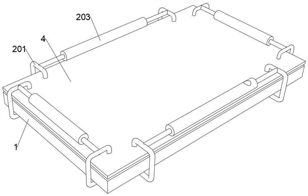
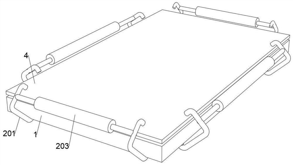
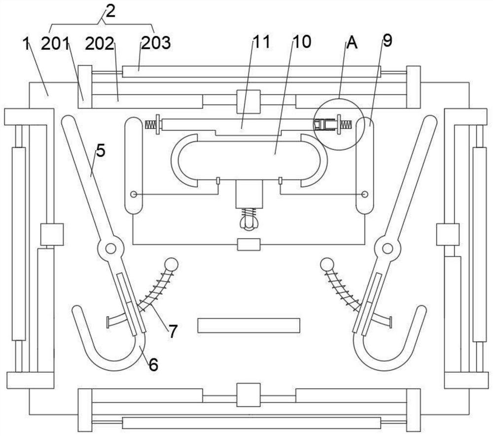
[0036] see figure 1 , figure 2 , image 3 , Figure 4 and Figure 8 , a clamping device for preventing the display screen from falling off, the device includes a clamping mechanism 2 for clamping the display backplane 1 and the display screen 4, and a magnetic drive mechanism for driving the clamping mechanism 2 to rotate, and the magnetic force The driving mechanism includes a first driving rod 5, an electromagnetic sheet 9, a heat conduction shell 10, a hot-melt metal 18, a partition plate 19, a limit ring 20 and a memory metal 21, and the heat conduction shell 10 is fixedly connected to the display backplane 1, A hot-melt metal 18 is placed inside the heat conduction shell 10, and a partition plate 19 is attached to one side of the heat conduction shell 10. The lower end of the divider plate 19 is fixedly connected with a memory metal 21, and one side of the memory metal 21 is engaged Connected to the limit ring 20 and the other side is fixedly connected to the partiti...
Embodiment 2
[0043] see figure 1 , figure 2 , image 3 , Figure 4 , Figure 5 and Figure 11 , on the basis of the above embodiment, one end of the first driving rod 5 is slidably connected to the second driving rod 6, and the end surface of the second driving rod 6 is connected to the universal joint 8 in rotation, and the universal joint 8 is sleeved on the limit The rod 7 is elastically connected to the limit rod 7 , and the limit rod 7 is fixedly connected to the display backplane 1 .
[0044] The second driving rod 6 is U-shaped or L-shaped.
[0045] When the electromagnetic sheet 9 drives the first drive rod 5 to rotate by magnetic force, the second drive rod 6 that is slidingly connected to the first drive rod 5 will stretch out under the limit action of the universal joint 8 and the limit rod 7, thereby The purpose of resisting the clamping mechanism 2 on the other side is achieved, so that the purpose of simultaneously driving multiple clamping mechanisms 2 to expand and c...
Embodiment 3
[0048] see figure 1 , figure 2 , image 3 , Figure 4 , Figure 6 and Figure 7 , on the basis of the above-mentioned embodiments, the clamping mechanism 2 includes a frame body 201 and a conflict plate 202, the frame body 201 is elastically connected to the back of the display back panel 1 through a spring, and one or two conflict plates are fixedly connected to the frame body 201. The plate 202 is located on the movement stroke of the corresponding first driving rod 5 or the second driving rod 6 .
[0049] The spring can make the frame body 201 reset automatically after the first driving rod 5 or the second driving rod 6 is removed.
[0050] The clamping mechanism 2 also includes a glue filling cylinder 203, the frame body 201 is a hollow structure, the frame body 201 and the glue filling cylinder 203 are connected, the glue filling cylinder 203 is filled with glue, and the frame body 201 is provided with a glue injection port. The glue port is located at the edge of ...
PUM
 Abstract
Description
Claims
Application Information
 - R&D
- Intellectual Property
- Life Sciences
- Materials
- Tech Scout
- Unparalleled Data Quality
- Higher Quality Content
- 60% Fewer Hallucinations
Browse by: Latest US Patents, China's latest patents, Technical Efficacy Thesaurus, Application Domain, Technology Topic, Popular Technical Reports.
© 2025 PatSnap. All rights reserved.Legal|Privacy policy|Modern Slavery Act Transparency Statement|Sitemap|About US| Contact US: help@patsnap.com


