Eureka AIR delivers breakthrough ideas for toughest innovation challenges, trusted by R&D personnel around the world.

Electric melting plasma moment composite furnace device and method thereof for treating dangerous waste materials

A plasma moment and material technology, which is applied in the field of ion moment compound furnace device, can solve the problems of limited heating range, many harmful components, and large heat energy loss, so as to ensure the uniformity of material distribution, improve the processing efficiency, and ensure the bottom temperature.

Pending Publication Date: 2021-12-24
金川镍钴研究设计院有限责任公司 +1
View PDF1 Cites 0 Cited by
  • Summary
  • Abstract
  • Description
  • Claims
  • Application Information

AI Technical Summary

Problems solved by technology

[0004] 1. It obtains sufficient flue gas residence time and reducing atmosphere through the gasification transition section, so as to partially treat the flue gas and reduce the harmful components of the flue gas, but its treatment of the flue gas is still incomplete, and the flue gas emitted There are still many harmful components, which cannot fully meet the current requirements for harmless treatment;
[0005] 2. When the flux electrode heated at the bottom of the melting chamber is in use, there will always be failures and malfunctions;
[0006] 3. The plasma torch is a flame cluster and cannot go deep into the melt. It can only heat the melt by heating the air on the surface of the melt, and the air conducts heat on the surface of the melt to heat the melt. It is an indirect heating method, which leads to large heat loss and limited heating range. The heat obtained by the receptor is much lower than the heat generated by the plasma torch, resulting in waste of energy;
[0007] 4. It is fed from one side, resulting in uneven distribution of materials in the melting chamber, which is not conducive to subsequent heating treatment

Method used


Image

  • Electric melting plasma moment composite furnace device and method thereof for treating dangerous waste materials
  • Electric melting plasma moment composite furnace device and method thereof for treating dangerous waste materials
  • Electric melting plasma moment composite furnace device and method thereof for treating dangerous waste materials

Examples


Embodiment 1

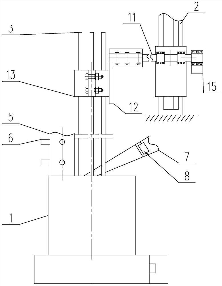
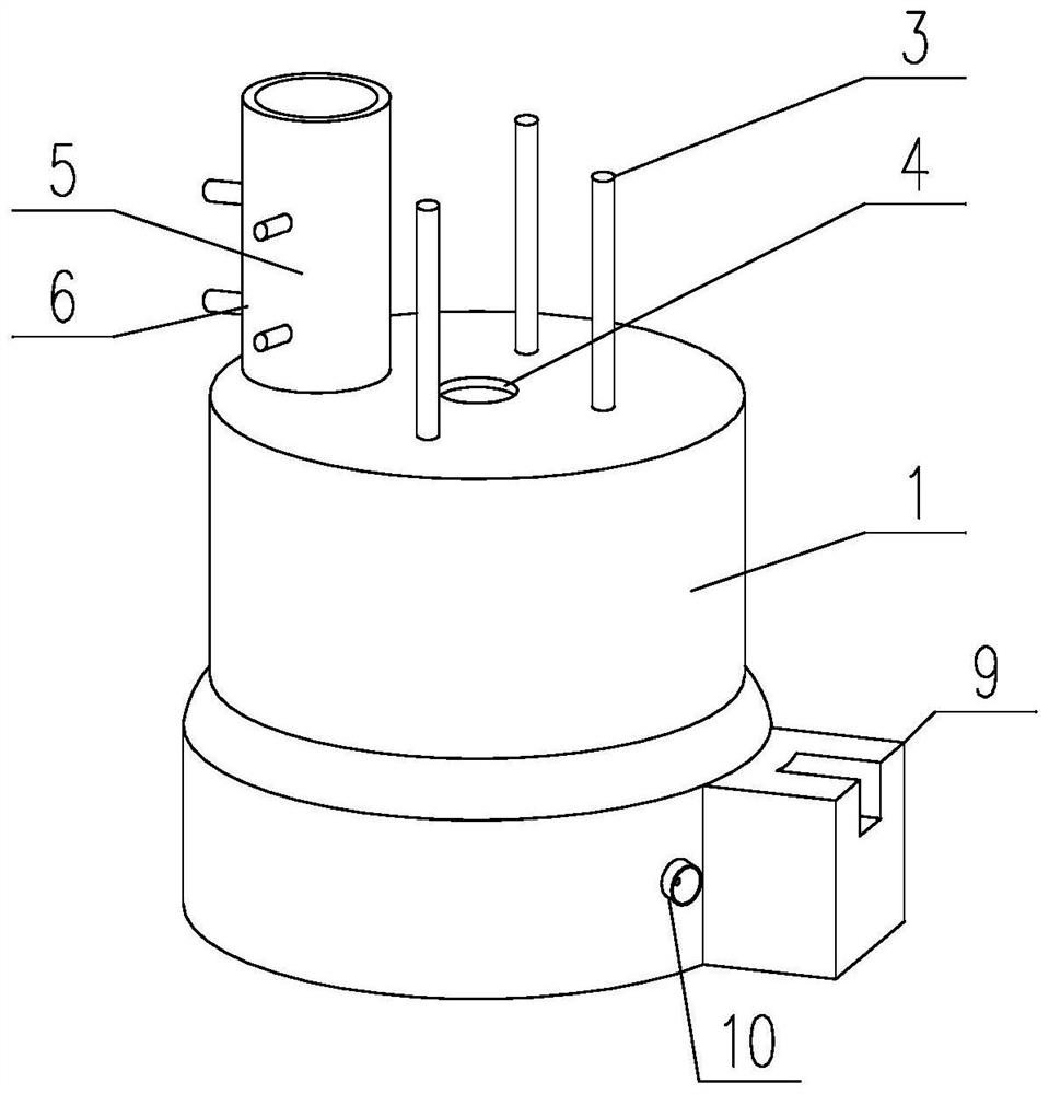
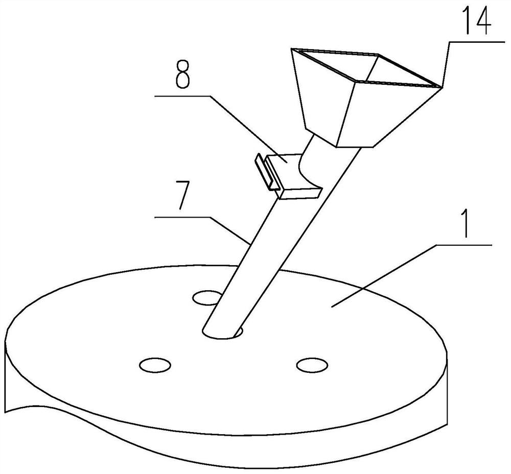
[0038] like Figures 1 to 3 As shown, an electric fusion plasma moment compound furnace device for processing hazardous waste materials includes an electrode 3 for heating the material at the bottom of the furnace body 1, and the electrode 3 is vertically movable on the furnace body 1, and it is placed The vertical linear drive mechanism 2 on one side of the furnace body 1 is driven up and down to adjust the distance between the bottom end of the electrode 3 and the bottom of the furnace body.

[0039] The vertical linear drive mechanism can be a cylinder, an oil cylinder, a lead screw module, a rack and pinion combination, a hoist, etc. In this embodiment, the vertical linear drive mechanism preferably adopts a lead screw module, and its housing is vertically fixed on the ground or other bearing platforms, and the driving slider threaded with the lead screw is connected to one end of the cross bar 11, and the The other end of the rod 11 is fixed on the vertical plate 12 , so...

Embodiment 2

[0044] like Figures 1 to 3 As shown, an electric fusion plasma moment compound furnace device for processing hazardous waste materials includes an electrode 3 for heating the material at the bottom of the furnace body 1, and the electrode 3 is vertically movable on the furnace body 1, and it is placed The vertical linear drive mechanism 2 on one side of the furnace body 1 is driven up and down to adjust the distance between the bottom end of the electrode 3 and the bottom of the furnace body. The feed inlet 4 of the furnace body 1 is arranged at the top center thereof. There are preferably three electrodes, which are distributed symmetrically along the center of the furnace body axis. The center of the furnace body 1 is equipped with a feed inlet, which can make the distribution of hazardous waste in the furnace body more uniform. Specifically, the feed inlet is located in the center of the three electrodes to ensure that the hot zone and the cold zone in the radial directio...

Embodiment 3

[0055] A method for processing hazardous waste materials, the method is implemented based on the device in any one of the above embodiments, which includes the following steps:

[0056] S1, put the hazardous waste materials to be processed into the furnace body 1;

[0057] S2. Start the vertical linear drive mechanism 2 to move the electrode 3 downward and insert it into the hazardous waste material, then stop the vertical linear drive mechanism 2;

[0058] S3, energize the electrode 3, and perform capacitive treatment of hazardous waste materials;

[0059] S4, start the vertical linear drive mechanism 2, so that the distance between the bottom of the electrode 3 and the top of the metal layer at the bottom of the hazardous waste heated to a molten state is L, and then stop the vertical linear drive mechanism 2;

[0060] S5, repeat step S4 regularly, keep the distance L between the electrode and the metal layer, until the metal in the metal layer is discharged;

[0061] S6. ...


PUM


Abstract

The invention discloses an electric melting plasma moment composite furnace device and method thereof for treating dangerous waste materials, and relates to the technical field of harmlessness of dangerous materials. The technical problems that the quantity of harmful components in smoke discharged by an existing furnace body for treating the dangerous waste materials is still large, and the working efficiency of the furnace body is low are solved. The device comprises an electrode for heating materials at the bottom of the furnace body, the electrode is vertically and movably arranged on the furnace body, and the electrode is driven up and down through a vertical linear driving mechanism arranged on one side of the furnace body so as to adjust the distance between the bottom end of the electrode and the bottom of the furnace body. The height of the electrode can be adjusted through the vertical linear driving mechanism, an electrode heating area can be located in the center of a melt, the bottom temperature is guaranteed, the height position of the electrode can be adjusted according to the thickness of a metal deposition layer, therefore the frequency of shutdown and metal discharging operation is reduced, and the dangerous waste treatment efficiency is improved.

Description

technical field [0001] The invention relates to the technical field of harmless treatment of hazardous materials, and more specifically relates to the technical field of an electric melting plasma moment compound furnace device and a method for treating hazardous waste materials. Background technique [0002] When recycling hazardous waste such as automobile oil filter elements, liquid crystal display glass, paint buckets, waste oil, and waste liquid, they are mainly incinerated in rotary kilns, and the residues after incineration in rotary kilns still belong to the category of hazardous waste. Therefore, Generally, it is further processed by electric furnace melting, plasma gasifier gasification, etc. [0003] Although the existing electric furnace melting can solve the problem of vitrification of the residue, the harmful gas generated during the melting process, and the direct discharge of harmful gas will pollute the atmosphere, so it needs to be further processed to be h...

Claims


Application Information

Patent Timeline
IPC IPC(8): F23G7/00F23G5/10
CPCF23G7/00F23G5/10F23G5/085F23G2204/201
Inventor 李祖如李维舟曾海龙于金龙王辉马淑林
Owner 金川镍钴研究设计院有限责任公司
Why Eureka
Eureka Blog
Learn More