Workbench for shaft processing and laser processing system based on workbench

A workbench and shaft technology, which is applied in the direction of furnace type, manufacturing tools, metal material coating process, etc., can solve the problem of easy bending deformation, limited effective processing length of laser cladding workbench, and inability to clamp slender shaft workpieces Avoid tightness and other problems, to achieve the effect of avoiding bending deformation, strong bearing capacity and convenient operation

Pending Publication Date: 2021-12-24
江苏珠峰光电科技有限公司
View PDF0 Cites 0 Cited by
  • Summary
  • Abstract
  • Description
  • Claims
  • Application Information

AI Technical Summary

Problems solved by technology

[0003] Most of the existing laser cladding workbenches have limited effective processing length, and most of them can only clad and quench some small and medium-sized workpieces, and cannot clamp some slender shaft workpieces. Bending deformation is easy to occur under clamping force. For this reason, we propose a large-load high-precision laser cladding rotary table applied to laser cladding and quenching of slender shafts to solve the above problems

Method used


Image

  • Workbench for shaft processing and laser processing system based on workbench
  • Workbench for shaft processing and laser processing system based on workbench
  • Workbench for shaft processing and laser processing system based on workbench

Examples


Embodiment Construction

[0029] The technical solutions of the present invention will be clearly and completely described below in conjunction with the accompanying drawings. Apparently, the described embodiments are some of the embodiments of the present invention, but not all of them.

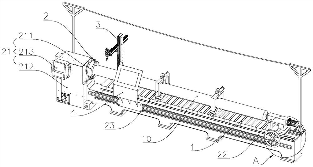
[0030] Such as figure 1 and 2 As shown, a workbench for shaft processing includes a horizontal bed 1, a clamping mechanism 2 and a laser module 3. The clamping mechanism 2 is arranged on the horizontal bed 1, and the clamping mechanism 2 is used for aligning shafts. The position of the part 10 is limited, and the laser module 3 is slidably arranged on one side of the horizontal bed 1 for processing the shaft part 10. The clamping mechanism 2 includes a three-jaw chuck 21, a moving tailstock 22 and several central support modules 23. The central support module 23 is arranged between the three-jaw chuck 21 and the movable tailstock 22, and the three-jaw chuck 21 and the movable tailstock 22 limit it from both ends of ...


PUM


Abstract

The invention relates to the technical field of laser cladding, in particular to a workbench for shaft processing and a laser processing system based on the workbench. The workbench comprises a horizontal lathe bed, a clamping mechanism and a laser module. The clamping mechanism is arranged on the horizontal lathe bed and used for limiting shaft parts. The laser module is arranged on one side of the horizontal lathe bed in a sliding manner and used for processing the shaft parts. The clamping mechanism comprises a three-jaw chuck, a movable tailstock and a plurality of center supporting modules. The center supporting modules are arranged between the three-jaw chuck and the movable tailstock. The three-jaw chuck and the movable tailstock limit the shaft parts from the two ends of the shaft parts. The center supporting modules limit the shaft parts from the main body portions of the shaft parts, and the shaft parts are stably arranged on the horizontal lathe bed. The center supporting modules support the shaft parts, then the movable tailstock with a centre locks the shaft parts, stable clamping of the to-be-machined shaft parts is achieved, the bearing performance is high, and stable processing is guaranteed.

Description

technical field [0001] The invention relates to the technical field of laser cladding, in particular to a workbench for shaft processing and a laser processing system based on the workbench. Background technique [0002] Laser cladding refers to placing the selected coating material on the surface of the cladding substrate in different ways of adding materials, melting it and a thin layer of the substrate surface at the same time through laser irradiation, and forming a very low dilution after rapid solidification. , a surface coating that is metallurgically combined with the substrate, a process that significantly improves the wear resistance, corrosion resistance, heat resistance, oxidation resistance and electrical properties of the base layer surface, cladding high-performance and high-strength alloys on the basis of cheap metals coating, so as to achieve the purpose of surface modification or repair, which not only meets the requirements for the specific performance of ...

Claims


Application Information

Patent Timeline
IPC IPC(8): C23C24/10C21D9/28C21D1/62
CPCC23C24/103C21D9/28C21D1/62C21D9/0025C21D9/0018
Inventor 葛伟伟陆轩然马骏胡一鸣施飞贺峰姜萍
Owner 江苏珠峰光电科技有限公司
Why Eureka
Try Eureka