Motor output shaft grinding device

A technology for output shafts and machine tools, which is applied in the direction of grinding drive devices, grinding machines, grinding frames, etc., and can solve the problems of mismatch between shaft parts and machine tool installation slots and low safety

Pending Publication Date: 2021-12-21
扬州科迪机电制造有限公司
View PDF0 Cites 0 Cited by
  • Summary
  • Abstract
  • Description
  • Claims
  • Application Information

AI Technical Summary

Problems solved by technology

[0002] As a common mechanical part, the shaft is used in various devices. When the shaft is upset during the application process, the shaft needs to be ground. When grinding, the shaft is first installed on the installation of the machine tool. On the groove, the shaft can rotate around the main shaft of the machine tool. At this time, the grinding wheel is held by hand, and the upsetting is eliminated through the relative movement of the grinding wheel and the shaft. However, when the shape of the shaft is not fixed, even the same shaft has the same diameter. It is gradually changing, which leads to the mismatch between the shaft and the installation groove of the machine tool, and the safety is low when the grinding wheel is operated by hand. For this reason, we propose a motor output shaft grinding device

Method used


Image

  • Motor output shaft grinding device
  • Motor output shaft grinding device

Examples


Embodiment Construction

[0013] The following will clearly and completely describe the technical solutions in the embodiments of the present invention with reference to the accompanying drawings in the embodiments of the present invention. Obviously, the described embodiments are only some, not all, embodiments of the present invention. Based on the embodiments of the present invention, all other embodiments obtained by persons of ordinary skill in the art without making creative efforts belong to the protection scope of the present invention.

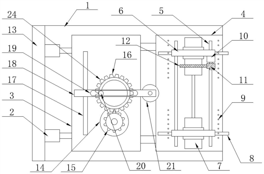
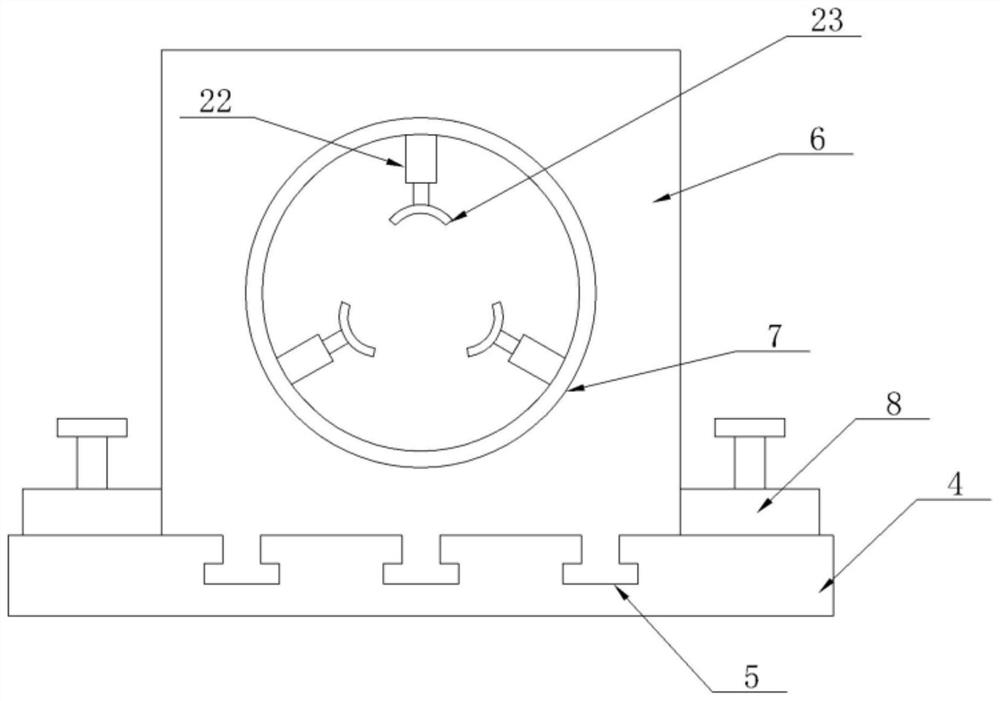
[0014] The invention provides a technical solution: a motor output shaft grinding device, please refer to Figure 1-2 , including the machine tool 1, the left side of the top outer wall of the machine tool 1 is provided with two groups of sliding grooves, the two groups of sliding grooves are provided with movable seats 3, and the right side of the outer wall of the top of the machine tool 1 is equipped with a fixed seat 4, in order to reduce weight, the fixed ...


PUM


Abstract

The invention discloses a motor output shaft grinding device in the technical field of motor maintenance. The motor output shaft grinding device comprises a machine tool, a front set of movable plate and a rear set of movable plate are slidably arranged in three sets of T-shaped sliding grooves, a gear is mounted at the output end of the front side of a driving motor, a gear ring is mounted at the front end of the annular outer wall of a mounting barrel on the rear side, the opposite ends of the gear ring an the gear are engaged, a grinding assembly is driven by electric-hydraulic push rods to move towards the right side to carry out grinding, the extension amount of the electric-hydraulic push rods can be adjusted through an upper computer or a control panel of the machine tool according to the diameter of a shaft piece and the depth to be ground, a motor drives a transmission gear and a driven gear to rotate, a sliding rod moves in an open groove, a movable plate is driven to move front and back, a grinding machine moves front and back to do grinding work, motor parameters can be adjusted through the upper computer or the control panel of the machine tool according to the length of the shaft piece, the number of turns of forward rotation and reverse rotation of the transmission gear is changed, and therefore rotation of the driven gear is changed, and the device adapts to the length of the shaft piece.

Description

technical field [0001] The invention relates to the technical field of motor maintenance, in particular to a motor output shaft grinding device. Background technique [0002] As a common mechanical part, the shaft is used in various devices. When the shaft is upset during the application process, the shaft needs to be ground. When grinding, the shaft is first installed on the installation of the machine tool. On the groove, the shaft can rotate around the main shaft of the machine tool. At this time, the grinding wheel is held by hand, and the upsetting is eliminated through the relative movement of the grinding wheel and the shaft. However, when the shape of the shaft is not fixed, even the same shaft has the same diameter. It is a gradual change, which causes the shaft to not match the installation groove of the machine tool, and the safety is low when the grinding wheel is operated by hand. For this reason, we propose a motor output shaft grinding device. Contents of th...

Claims


Application Information

Patent Timeline
Patent Type & Authority Applications(China)
IPC IPC(8): B24B5/04B24B47/22B24B41/02B24B47/04B24B47/12B24B41/06
CPCB24B5/045B24B47/22B24B41/02B24B47/04B24B47/12B24B41/06
Inventor 刘佳兵
Owner 扬州科迪机电制造有限公司
Why Eureka
Try Eureka