Three-station operating mechanism and switch cabinet

An operating mechanism and three-station technology, which is applied in the direction of electric switches, electrical components, circuits, etc., can solve the problem that the three-station operating mechanism cannot realize the complete interlock function, and the three-station operating mechanism and circuit breaker operation The mechanism cannot realize the complete interlocking function and other problems, and achieve the effect of compact structure, reliable use and good safety

Pending Publication Date: 2021-12-31
PINGGAO GRP +1
View PDF13 Cites 0 Cited by
  • Summary
  • Abstract
  • Description
  • Claims
  • Application Information

AI Technical Summary

Problems solved by technology

[0003] The purpose of the present invention is to provide a three-position operating mechanism to solve the problem that the current three-position operating mechanism cannot realize the complete interlocking function; the purpose of the present invention is to provide a switch cabinet to solve the current The problem that the three-position operating mechanism and the circuit breaker operating mechanism in the switchgear cannot realize the complete interlocking function

Method used


Image

  • Three-station operating mechanism and switch cabinet
  • Three-station operating mechanism and switch cabinet
  • Three-station operating mechanism and switch cabinet

Examples


Embodiment 1

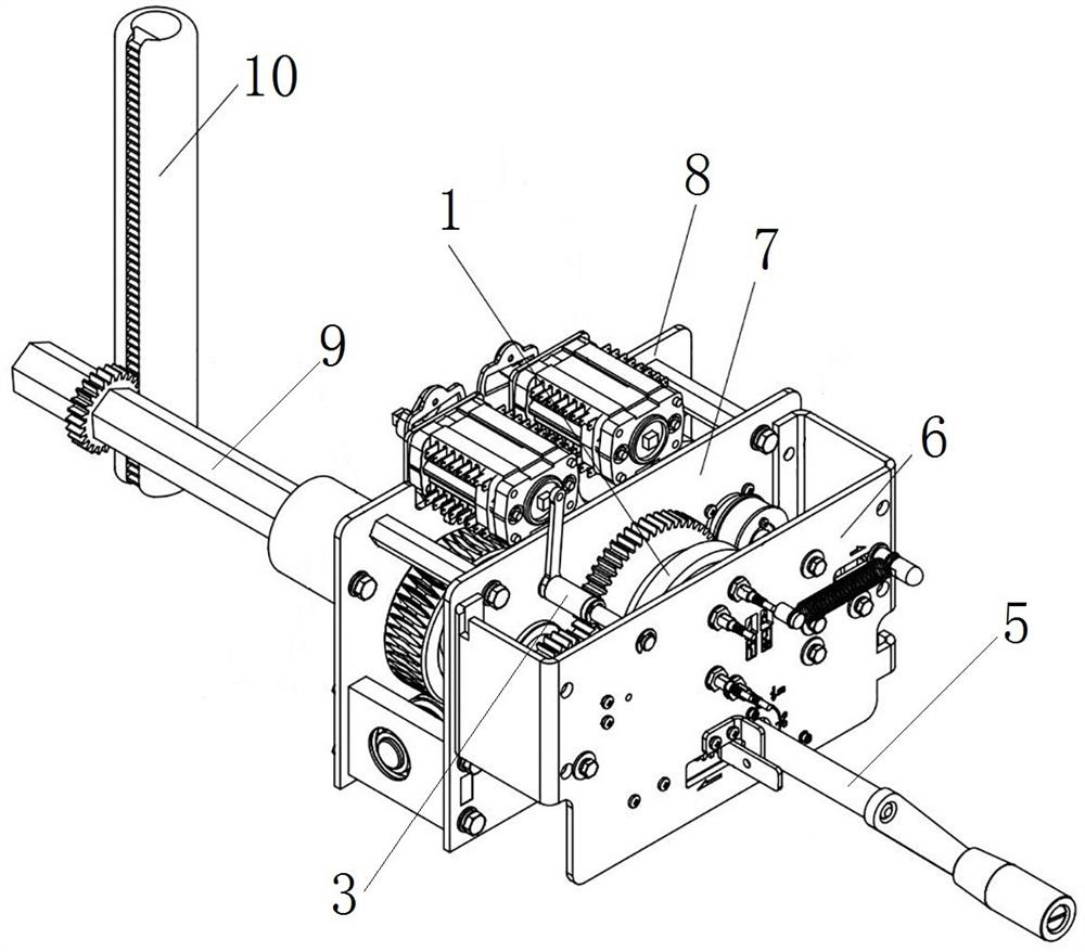
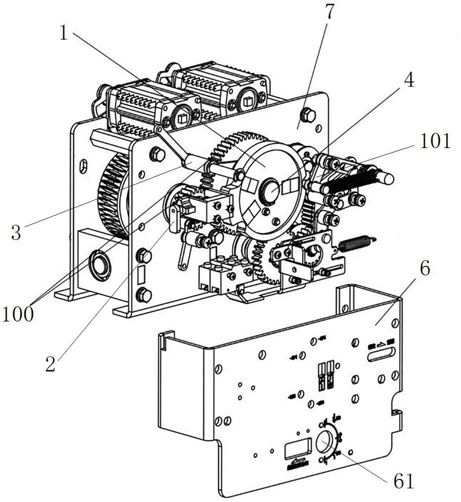
[0070] Such as figure 1 with figure 2 As shown, the three-position operating mechanism includes a mounting frame and a transmission assembly installed on the mounting frame. The mounting frame includes a panel 6, a front mounting plate 7 and a rear mounting plate 8 arranged in sequence. The transmission assembly has an input end and an output end. The input end is used for operating torque input, the output end includes an output shaft 9, and the output shaft 9 is used to drive the moving contact 10 of the three-position switch to operate. An operating hole 61 is provided on the panel 6 for inserting the operating handle 5 into the input end during manual operation.

[0071] The drive shaft 4 is also installed on the mounting bracket, and the drive shaft 4 is connected to the transmission assembly in a transmission manner. Under the action of the input torque, the transmission assembly drives the drive shaft 4 to rotate. In this embodiment, the drive shaft 4 and the transmis...

Embodiment 2

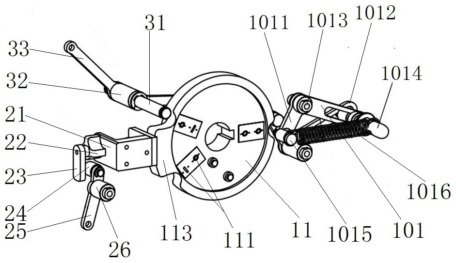
[0095] The difference between this embodiment and Embodiment 1 is that the second mating surface in Embodiment 1 is formed by the groove wall surface of the cam groove, while in this embodiment, the locking dial includes a front disk, a middle disk and a For the rear end cam, the third mating surface is arranged on the front plate, the first mating surface is arranged on the middle disk, and the second mating surface is directly formed by the outer peripheral surface of the rear end cam. At this time, the reverse interlocking mechanism also includes a Spring to maintain the position of the second lock.

Embodiment 3

[0097] The difference between this embodiment and Embodiment 1 is that the positive interlocking groove in Embodiment 1 is provided on the outer peripheral surface of the interlocking turntable and the notch is radially outward, while in this embodiment, the positive interlocking groove It is arranged on the disk surface of the interlocking turntable, the forward interlocking groove is an annular groove, and the annular groove has a concave part, and the concave part is used to form a first locking section for the first locking part to snap in. Correspondingly, the first locking The component is located on the disk side of the interlocking turntable, and the groove wall surface of the annular positive interlocking groove is used to form the first mating surface.


PUM


Abstract

The invention relates to a three-station operating mechanism and a switch cabinet. The three-station operating mechanism comprises a locking turntable, a forward interlocking mechanism and a reverse interlocking mechanism, wherein the locking turntable is arranged on a driving shaft, and the locking turntable is provided with a first matching surface and a second matching surface; the forward interlocking mechanism comprises a first locking piece, when the circuit breaker is in a closed state, the first locking piece acts to be matched with a first locking section of the first matching surface to lock the locking turntable, and when the circuit breaker is in an open state, the first locking piece is driven by a circuit breaker operating mechanism to be separated from the first locking section so as to unlock the locking turntable; the reverse interlocking mechanism comprises a second locking piece, when the three-position switch is in a position switching state, the second locking piece is matched with a second locking section of the second matching surface to lock the circuit breaker operating mechanism, when the three-position switch is in any one of the three positions, the second locking piece is matched with a second locking section of the second matching surface to lock the circuit breaker operating mechanism, the second locking piece is matched with the second unlocking section of the second matching surface so as to unlock the circuit breaker operating mechanism; and the three-position operating mechanism and the circuit breaker operating mechanism can form complete interlocking.

Description

technical field [0001] The invention relates to a three-station operating mechanism and a switch cabinet. Background technique [0002] The three-position operating mechanism is an operating mechanism that drives the three-position switch to switch among the three positions of closing, isolation and grounding. Through the input torque to the operating input end of the operating mechanism, the internal transmission structure of the operating mechanism The movable contact of the switch is driven to act, and the three-station operating mechanism has a closing station, an isolating station and a grounding station corresponding to the three position states of the three-station switch. According to the new functional requirements, the switchgear needs to use circuit breakers and three-position switches at the same time, and this kind of switchgear needs to have an interlock function between the circuit breaker operating mechanism and the three-position operating mechanism to avoid...

Claims


Application Information

Patent Timeline
Patent Type & Authority Applications(China)
IPC IPC(8): H01H9/20
CPCH01H9/20
Inventor 费翔朱志豪马明乐卢留洋王海燕袁端磊韦磊张庆飞郭峰朱启媛
Owner PINGGAO GRP
Why Eureka
Try Eureka